


Ⅰ. INTRODUCTION
5 th generation(5G)mobile communication has broad po-tential applications owing to its enhanced capabilities in terms of high data rate, high reliability and low latency. Relevant technologies, such as the Internet of things(IoT)[1], artificial intelligence (AI)[2], cloud computing[3], and big data analytics[4]under rapid development may change the daily life of everyone in the world. 5G wireless systems capable of better supporting the above technologies are expected to be ready for commercial operation around 2020.
In 2016, the European Commission (EC) announced its spectrum plan for 5G trials covering the bands from 3. 4 to 3. 8 GHz; the 3. 8-4. 2 GHz bands are reserved for future applications. In 2017, China’s Ministry of Industry and Information Technology(MIIT)officially declared that 3. 3-3. 4(indoor only), 3. 4-3. 6 and 4. 8-5 GHz bands are allocated for 5G service, and the 3. 6-4. 2 GHz bands are considered for future 5G allocation[5]. As shown in Fig.1, the available frequency spectra for most countries or regions are mostly within the frequency bands from 3. 3 to 4. 2 GHz. The so-called sub-5-GHz bands are very important for 5G trails and future deployment. Therefore, it is highly desirable to cover this band for the proposed base station antenna.
Because of the existence of rich multipath deployment and scattering propagation in typical mobile channels, the receiving signals usually yield an elliptical polarization. To mitigate multipath fading and to increase channel capacity, a dualpolarized antenna array can be used for 5G base stations. In addition, compared with 0° and 90° dual-polarized antenna arrays, antennas with ±45°polarization can have a higher efficiency because the two antenna masts can be used to receive data simultaneously[6].
With regard to the feeding structures, a Y-shaped feeding line has been developed for a dual-polarized array and the array achieves a wide impedance bandwidth from 1. 7 to 2. 7 GHz with standing wave ratio(SWR)less than 1. 5. The isolation between the two orthogonal ports is larger than 25 dB[7]. Another ±45° dual-polarized array with two crossed bowtie elements has been designed for the same long term evolution(LTE)bands, and the antenna element has a wide halfpower beamwidth of about 65°[8]. To enhance the impedance bandwidth, additional loops are embedded into a loop dualpolarized antenna and a new resonant mode is generated, as discussed in Ref. [9]. A dual-dipole dual-polarized structure has also been proposed that has a broad bandwidth of 51% (1. 61-2. 71 GHz)and high isolation of larger than 30 dB[10]. However, the above designs focus on LTE applications only.
Multiple-input multiple-output(MIMO)technology, especially a massive one, is an enabler for 5G mobile communication. To achieve the optimum MIMO performance, several parameters such as the bandwidth, gain, isolation, and crosspolarization levels are necessary to evaluate the antenna element. A side-view profile of the element is also important for aesthetical reasons. Many decent designs have been reported in recent years to meet these requirements.
Figure 1
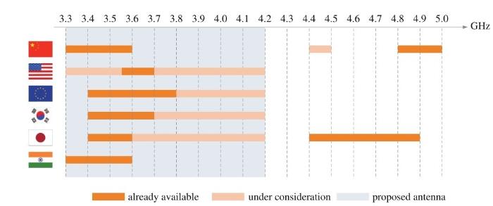
Figure 1
Allocated frequency spectra for 5G wireless communications in major countries
For instance, three arcs with different length are placed at the back side of the dipole to achieve a low profile structure in Ref. [11]. In addition, low mutual coupling levels are achieved with a novel layout of four MIMO elements. A broadband MIMO antenna with three low-profile elements is proposed in Ref. [12]for indoor distributed antenna systems; this design can be conveniently extended to more MIMO elements while keeping the low-profile merit.
In this paper, a dual-polarized antenna array is developed for a 5G base station in the sub-5-GHz bands. A low-profile antenna element is introduced in section Ⅱ. Two kinds of Hshaped elements are proposed for improving the isolation between the antenna elements in section Ⅲ. Several important element parameters concerning MIMO performance, including the envelope correlation factor and the radiation pattern, are illustrated in section Ⅳ. The paper is concluded in section V.
Ⅱ. DESIGN OF THE DUAL-POLARIZED ANTENNA ELEMENT
The proposed dual-polarized antenna element is illustrated in Fig.2. The antenna element consists of two orthogonally placed bowtie antennas, a dielectric substrate(i. e. , AD255C), a planar metallic reflector, two feeding coaxial lines, and four plastic cylinders for fixing the element at the four corners. This structure is similar to the bowtie element proposed in Ref. [8], but the proposed one is more compact in size. The dimensions of the metallic plate and dielectric substrate for one antenna element are L1 × W1=100 mm × 100 mm and L2 ×W2 × H2=40 mm × 40 mm × 0.8 mm, respectively. The profile between them is H1=20 mm.
The antenna element consists of two fan-shaped arms with radius r1=15 mm and an open angle α=84°. The two arms are placed at the top and bottom sides of the dielectric substrate, respectively. The geometric centers of the fan-shaped arms are at a distance of 0.35 mm away from the center of the dielectric substrate and the distance between the two centers of the arms is 0.25 mm. One arm of the−45°dipole antenna that is placed at the front side is connected to a tiny rectangular metal sheet and then connected to the outer conductor of the coaxial line. The inner conductor of the coaxial line is connected to the other arm of the−45° antenna on the back side. The length and width of the sheet are 3 mm and 1 mm, respectively. Similarly, the arms of the+45° dipole antenna placed at the front and back sides are connected to the inner and outer conductors of the coaxial line, respectively. There is also a tiny metal sheet on the back side of the same size of the one on the front side.
Figure 2
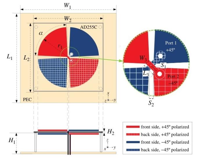
Figure 2
Structural configuration of the proposed dual-polarized antenna element
Ports 1 and 2 correspond to the +45° polarized dipole and the−45° polarized one, respectively. The simulated Sparameters of the dual-polarized antenna element are illustrated in Fig.3. It can be observed that the antenna element covers the frequency band from 3. 4 to 5 GHz(S11< −10 dB, 38%). There is a metallic hole on antenna 2 for fitting the coaxial line structure. As a result, S22 of Port 2 is a little different from S11 of Port 1, but it still covers the frequency bands of 3. 5-4. 8 GHz. However, the isolation between Ports 1 and 2 is reduced. For the sake of convenience, the isolation between different antenna elements is discussed by using a lumped port in the following part. The bandwidth of the antenna element is 3. 2-4. 7 GHz, and the mutual coupling is around−25 dB. A comparison of two different elements with open angles of α=84°and 90°is shown in Fig.4. The impedance matching property of the antenna element with α =84° is better than the one with α=90°.
Figure 3
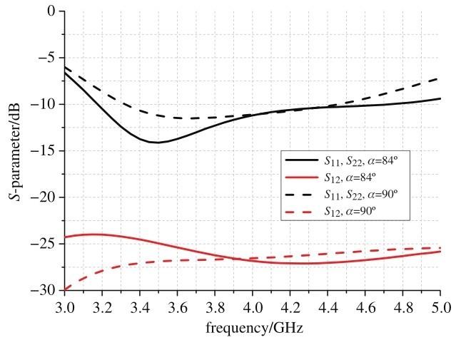
Figure 3
Simulated S-parameters of the antenna element with different feeding settings
Figure 4

Figure 4
Simulated S-parameters of the antenna element with different fan angles
Ⅲ. DESIGN OF THE ANTENNA ELEMENT WITH AN H-SHAPED COUPLING ELEMENT
It is not easy to improve the isolation between two antennas working at the same resonant frequency, if the two antennas are placed in close proximity. In Ref. [13], an additional coupling element is proposed for decoupling two identical dipole elements in close proximity, as shown in Fig.5. The introduction of an H-shaped coupling element cancels the transmitting field between the two dipole antennas, thereby improving antenna isolation. The H-shaped element can assume two-or three-dimensional forms, and a 7 dB reduction of mutual coupling is achieved at its resonant frequency with suitable parameters for the H-shaped element[13]. However, this method will affect the radiation performance of the antenna and slightly reduce its bandwidth or change the resonant frequency.
Figure 5
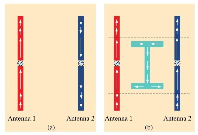
Figure 5
A coupling element for decoupling two identical dipole elements in close proximity: (a)Illustration of two center-fed dipole antennas; (b)Current directions with the H-shaped coupling element
In this paper, a 2 × 2 MIMO antenna consisting of four proposed dual-polarized elements is considered. Two kinds of H-shaped coupling elements are introduced to reduce the mutual coupling.
A. Vertical Arrangement
The 2 × 2 MIMO antenna with two H-shaped coupling elements in a vertical arrangement is illustrated in Fig.6. The size of the metallic reflector is L4 × W4=162. 5 mm × 143 mm and the height of the antenna elements is H1 =20 mm from the reflector. The lateral and longitudinal distances between the adjacent antenna elements are D1=43 mm and D2=62. 5 mm, respectively. The four antenna elements are symmetrically placed on the printed circuit board(PCB)and the horizontal distance between the centers of the antenna elements and the center of the reflector is D3=37. 9 mm. For the convenience of description, “Pn±”is used to represent each port, where“n”is the port number and“±”indicates+45°or−45°polarization.
Two identical H-shaped coupling elements M1 and M2 are placed at the center of the PCB with the same height H1. The dimensions of the H-shaped metal sheet are as follows: W5=15 mm, L5=30 mm, and L6=W6=1 mm. The corresponding S-parameters of the antenna array are shown in Fig.7, and the performance for the original antenna array without Hshaped elements is given for comparison. Here, some typical S-parameters between the antenna elements with a potential of high mutual coupling levels are discussed for the sake of conciseness. Some curves are merged owing to the symmetry of the antenna array structure.
Figure 6

Figure 6
Illustration of a vertical arrangement of extra decoupling elements for the array with four dual-polarized antenna elements
Figure 7
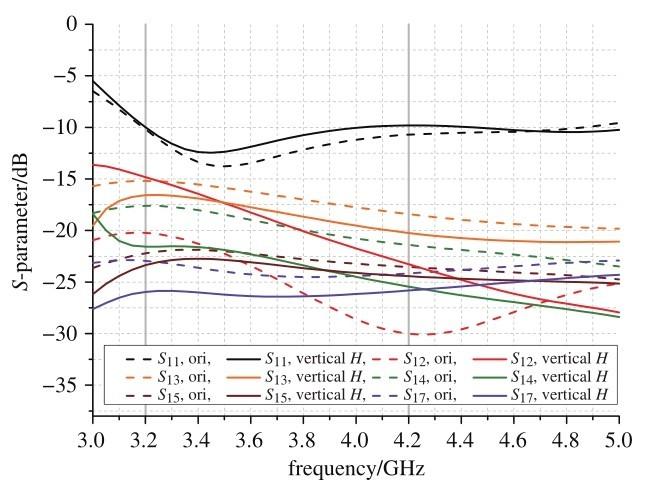
Figure 7
Simulated S-parameters for the four-element array with a vertical arrangement of extra decoupling elements
•Snn(n=1-8): The reflection coefficients of each antenna port. Compared with the results of the original antenna array, it is shown that the antenna bandwidth is almost unchanged with the H-shaped element(3. 2-4. 2 GHz, Snn< −10 dB).
•S13 (≈S24, S57, S68)and S17 (≈S46): Both S13 and S17 are reduced by∼2 dB within the frequency band of interest.
•S14(≈S23, S58, S67): These S-parameters are reduced by∼3. 8 dB within the frequency band of interest.
• S15 (≈ S26, S37, S48): These S-parameters are reduced by only∼0.9 dB. Fortunately, the original value of S15 is less than-20 dB and the improvement can be ignored.
•S12(≈S34, S56, S78): S12 is the only mutual coupling that is increase(by∼4 dB), especially from 3. 2 to 3. 8 GHz.
•The other S-parameters are less than−25 dB and can be ignored.
In summary, the additional H-shaped coupling elements in a vertical arrangement will improve most of the isolation between ports of MIMO antennas because of the isolation of the field caused by the additional element. However, it will also deteriorate isolation between different+45° and−45° arms in an array element. In addition, if we change the parameters of the H-shaped metal sheet, the S-parameter will change as well. S13 will be reduced by more than 10 dB when L5 is less than 25 mm, but Snn and S12 will become worse. As a result, there is a trade-off between bandwidth and isolation.
B. Crossed Arrangement
The MIMO antenna array with two additional H-shaped coupling elements in a crossed arrangement is illustrated in Fig.8. The main parameters and distance of the antenna element are unchanged when compared to the case discussed above. The crossed H-shaped metal sheet elements M1 and M2 are in the center of the reflector. The dimensions of the H-shaped metal sheet are as follows: W7 =15 mm, L7 =30 mm, and L8=W8=1 mm. M1 and M2 are placed at different planes and the vertical distance is H2=0.8 mm with different angles in+45°and−45°. There is a great difference in the Sparameters because of the asymmetric structure. Only typical S-parameters are illustrated in Fig.9. The optimized results for S11(≈S44≈S66≈S77)are better than those of S22(≈S33≈S55 ≈S88), and both of them cover from 3. 3 to 4. 3 GHz. S13(≈S24≈S57≈S68)is reduced by∼1 dB on average and S12(≈S34≈S56≈S78)is almost unchanged. However, as in the vertical arrangement case, isolation between Ports 2 and 3 (≈S58)and between Ports 2 and 8(≈S58)will become worse.
Ⅳ. PERFORMANCE OF THE MIMO ANTENNA UNIT
A. Envelope Correlation
In realistic mobile scenarios, signal fading occurs because of the environmental setting. The envelope correlation(ECC) is an important parameter for evaluating the performance of a MIMO antenna in typical multipath environments. In this section, the ECC of an array with four dual-polarized elements is evaluated. The H-shaped elements are in vertical arrangement, as shown in Fig.6. Some typical ECC values are given and discussed at three frequency points, i. e. , 3. 3, 3. 7 and 4. 2 GHz. The ECC between the different ports can be calculated by using the following expressions[14]:
Figure 8

Figure 8
Illustration of a crossed arrangement of extra decoupling elements for the array with four dual-polarized antenna elements
Figure 9
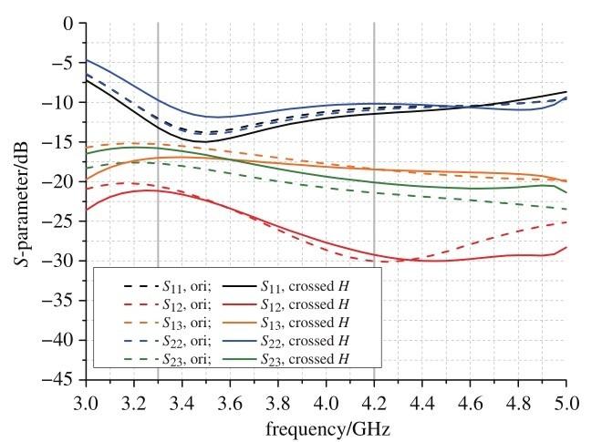
Figure 9
Simulated S-parameters for the four-element array with a crossed arrangement of extra decoupling elements
where the vertical-to-horizontal time-average power ratio XPR=Pv/Ph and the power angular density function Pθ =Pφ are equal to constants of 1 and 1/4π, respectively. These assumptions conform to the simplified scattering environment. Eθ and Eφ are the complex electric far field of the radiated waves in θ and φ polarization, respectively. ρ is the ECC values between different ports which are calculated using Eqs. (1)-(3) as the results listed in Tab.1. The average value of ρ is less than 0.05, an accepted range for base station applications.
Figure 10
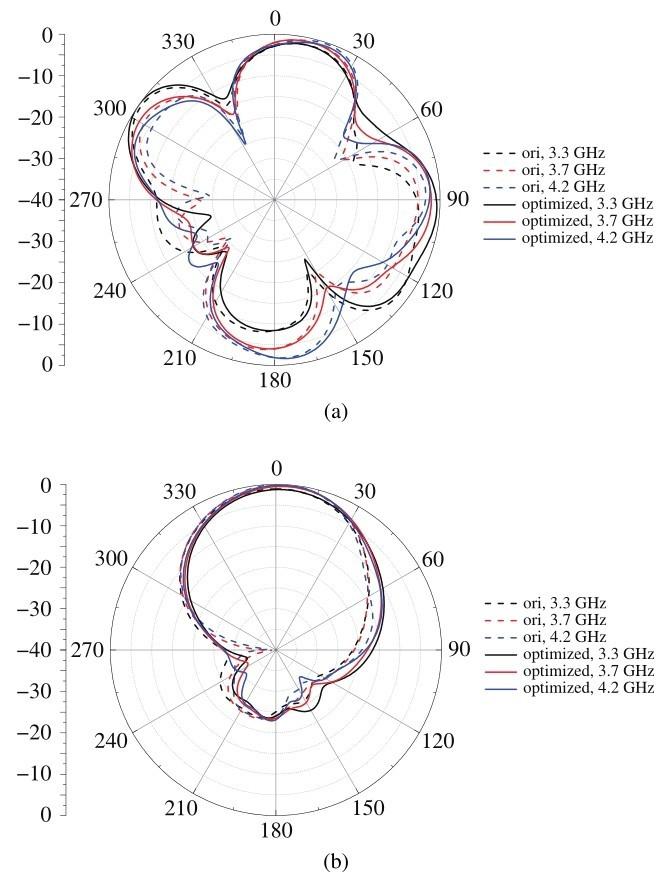
Figure 10
Simulated radiation patterns of the antenna element in: (a)the XY plane; (b)the YZ plane
B. Far-Field Radiation Pattern and Gain
A comparison of the far-field radiation pattern between the original MIMO antenna and the optimized MIMO antenna with H-shaped coupling elements in the vertical arrangement is shown in Fig.10. The XY and XZ planes are illustrated in Fig.10(a)and(b)at 3. 3, 3. 7, and 4. 2 GHz. It can be observed that the far-field radiation patterns of the two cases are almost identical at both XY and XZ planes.
The voltage standing wave ratio(VSWR)and realized gain of the MIMO antenna with H-shaped elements in the vertical arrangement are shown in Fig.11. The bandwidth is from 3. 2 to 5 GHz(VSWR< 2), which can cover the entire frequency band of 5G networks below 5 GHz. In addition, the realized gain of a single element is more than 7 dBi in this frequency band.
Table 1 ECC values of the antenna array with four dual-polarized elements and H-shaped decoupling elements
| frequency | ρ12 | ρ13 | ρ14 | ρ15 | ρ16 | ρ17 | ρ18 | average |
| 3.3 GHz | 0.010 2 | 0.106 0 | 0.069 9 | 0.026 1 | 0.059 8 | 0.048 7 | 0.002 3 | 0.046 1 |
| 3.7 GHz | 0.032 7 | 0.053 4 | 0.015 8 | 0.015 3 | 0.035 2 | 0.008 1 | 0.016 5 | 0.025 2 |
| 4.2 GHz | 0.031 0 | 0.035 4 | 0.010 3 | 0.002 5 | 0.024 5 | 0.001 5 | 0.024 5 | 0.018 5 |
Figure 11
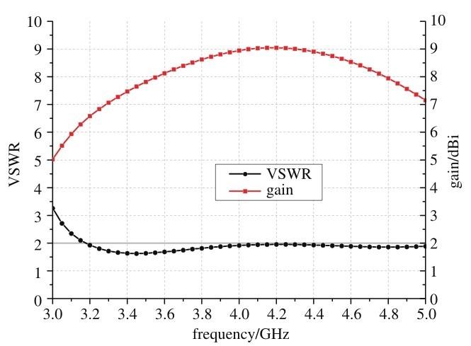
Figure 11
Simulated VSWR and gain of the antenna element
Ⅴ. CONCLUSION AND FUTURE WORK
In this paper, an additional H-shaped coupling element used to reduce the mutual coupling is proposed and verified in a 2 × 2, ±45°dual-polarized MIMO antenna. The proposed antenna can cover the main frequency band of 5G mobile networks and offers good performance in terms of ECC, gain, and radiation pattern. Our main future work will be to optimize the H-shaped metal sheet and antenna performance.
Reference
Internet of things in the 5G era: enablers,architecture,and business models
[J].
Smart home and smart city solutions enabled by 5G,IoT,AAI and CoT services
[C]//
EMC: Emotion-aware mobile cloud computing in 5G
[J].
Mobile cloud sensing,big data,and 5G networks make an intelligent and smart world
[J].
High isolation dual polarized antenna system using dipole radiating elements: U.S.Patent 5,952,983
[P]. 1999-9-14.
Chu,D.L.Wen,Y.Luo.A broadband ±45°dual-polarized antenna with Y-shaped feeding lines
[J].
A broadband dual-polarized planar antenna for 2G/3G/LTE base stations
[J].
A multimode wideband ±45°dual-polarized antenna with embedded loops
[J].
Broadband dual-polarized dual-dipole planar antennas for base station applications: analysis,design,and application for base stations
[J].
Design of a low-profile MIMO antenna for 698-2700 MHz LTE femtocell base stations
[J].
Link-level analysis of a multiservice indoor distributed antenna system[wireless corner]
[J].
Isolation enhancement between two closely packed antennas
[J].
Design of a MIMO dielectric resonator antenna for LTE femtocell base stations
[J].
