


Ⅰ. INTRODUCTION
In comparison with conventional MIMO systems, there are some new challenges in massive MIMO systems. Because massive MIMO systems contain tens or even hundreds of antenna elements, many problems still require further study. One important issue is the system complexity of massive MIMO arrays. Because there are many antenna elements, many radio frequency(RF)chains should be utilized to excite the elements, which results in high system complexity and expense. To solve the complexity problem, several studies have been conducted and possible solutions have been proposed[6,7,8,9,10,11,12,13].
One possible solution is antenna selection[6,7,8], in which some antenna elements are selected from all the elements to reduce the number of RF chains. Spatial modulation is another solution, which takes antenna patterns into consideration and reduces the number of RF chains[9,10]. However, these methods are only applicable to linear arrays. Reducing RF chains in two-dimensional (2D) arrays is still a challenging problem. Other approaches, such as the use of electromagnetic lens-focusing antennas[11] and beamspace MIMO[12], have been proposed to alleviate the 2D array complexity problem in massive MIMO systems. However, the RF chains in these methods must be able to handle a high power capacity, which is unacceptable in practical massive MIMO applications[13].
Recently, a new method, vertical spatial filtering (VSF), is proposed to achieve low-RF-complexity massive MIMO systems[14]. In urban macro (UMa) cellular networks, the technique can reduce the RF-complexity in the vertical dimension of 2D antenna arrays. Because the VSF technique only conducts beam mapping in the vertical dimension, a 2D antenna array does not suffer from the power capacity problem. Moreover, three-dimensional(3D)channel model simulation shows that the performance achieved when the VSF technique is applied is close to that of complete systems in UMa cellular networks. However, only theoretical analyses are presented in Ref. [13]. An antenna array design strategy is still needed to demonstrate that the VSF technique is realizable in practical applications.
In this paper, a multiple fan-beam antenna array is proposed based on the VSF technique. The proposed antenna array consists of eight subarrays. Every subarray has eight printed dipole elements and a specific beam mapping network. Each subarray achieves two fan beams at ±7°with two feeding ports, which is an acceptable base station configuration[13]. Thus, the proposed antenna array comprises 64 printed dipole elements and only 16 RF chains. In comparison with a conventional complete massive MIMO system, which requires 64 RF chains, the proposed antenna array is realized with relatively low system complexity. A prototype of the proposed antenna array is fabricated to validate the design strategy. The measured results demonstrate that the antenna array achieves two fan beams at ±7°, and the measured gain of every port is higher than 10 dBi.
Ⅱ. SUBARRAY DESIGN
The proposed antenna array consists of eight subarrays. The subarray topology is shown in Fig.1. By using a microstrip line feeding network and four hybrid couplers, the subarray can achieve two kinds of phase distribution for the antenna elements. When port 1 is excited, the 45° phase shifter, 22. 5° phase shifters, and 90° hybrid couplers make a −22. 5° phase step from antenna element 1 to element 8. Thus, the radiation pattern points at−7°in the E plane. Similarly, when port 2 is excited, the phase step is 22. 5°, and the radiation pattern points at 7°in the E plane.
Figure 1
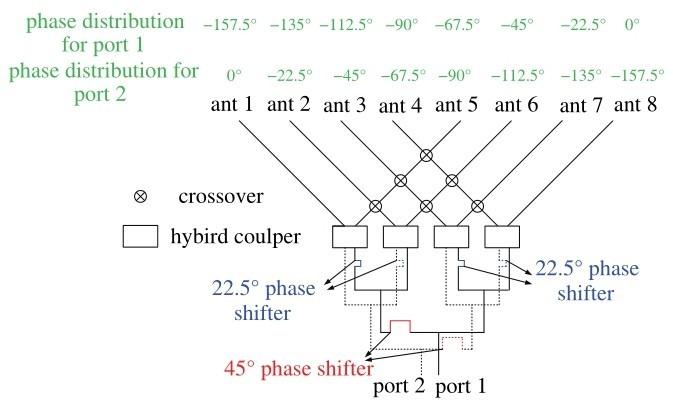
Figure 1
Schematic diagram of the proposed subarray
Based on the schematic diagram, a simulation model is designed, as illustrated in Fig.2. Each subarray uses eight printed dipole antennas as radiation elements. The printed dipoles antennas are excited by a microstrip line, as shown in Fig.2(a). Fig.2(b)shows the front view of the proposed subarray. By using three Wilkinson power dividers, the microstrip line feeding network connects with four hybrid couplers. As shown in Fig.2(b)and(c), the 22. 5° and 45° phase shifters are achieved by using a phase delay line. In addition to the hybrid couplers, there are six crossover structures. Because the crossover structure affects the phase delay, six phase compensation structures are utilized to correct the phase distribution. To excite the antenna elements through port 2, another microstrip line feeding network is soldered back-to-back with the abovementioned circuit. Fig.2(d)shows the structure of the hybrid coupler in detail. A jumper wire is used to connect the hybrid coupler and the microstrip line.
Ⅲ. COMPLETE ANTENNA ARRAY
The proposed subarrays can be utilized for beam mapping in the vertical dimension. For a massive MIMO system, 2D arrays are necessary for beam mapping in the horizontal plane. In the proposed antenna array structure, eight subarrays are combined to achieve the complete antenna array, as shown in Fig.3. In the complete array, all of the subarrays are identical. Each subarray has two ports and radiates two fan beams in the vertical plane. There is also a reflector in the proposed array. The reflector is a metal surface located behind the printed dipole antennas. Fig.4 shows the simulated radiation patterns, which illustrates the effect of the reflector. As shown in Fig.4, both radiation patterns point at 7°. However, the gain increases to 3. 6 dB when there is a reflector, and the front-to-back ratio is improved by more than 15 dB. Moreover, simulated results, which are not shown for simplicity, indicate that the reflector also improves the isolation between printed dipole elements.
Figure 2
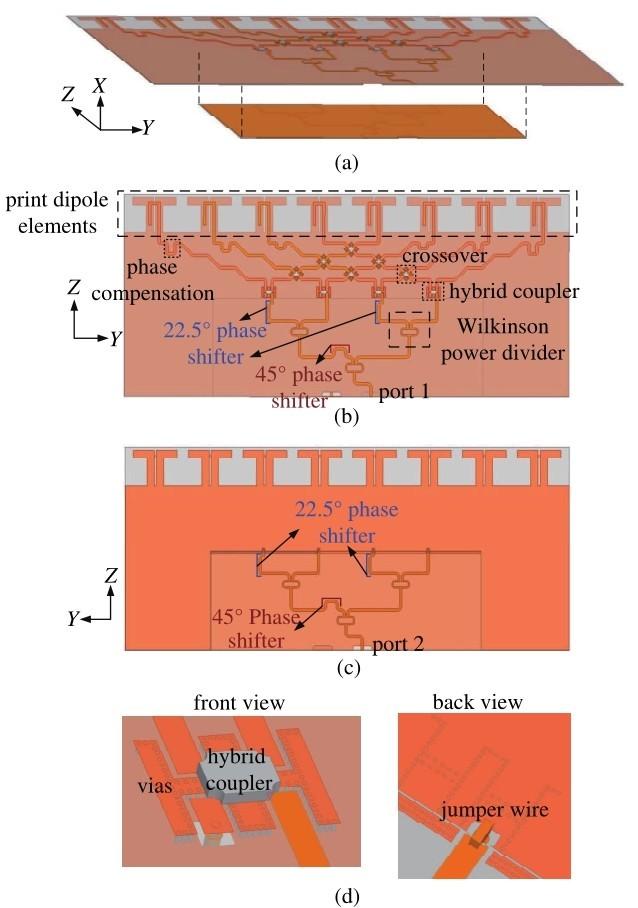
Figure 2
Simulated model of the proposed subarray: (a)perspective view; (b)front view; (c)back view; (d)detailed structure of the hybrid coupler
Ⅳ. MEASUREMENT RESULTS
A prototype of the proposed antenna array is fabricated to validate the design strategy. Fig.5 shows the photographs of the subarray. The subarray is fabricated on an F4B substrate (εr =2. 65). The dimension of the larger substrate is 470 × 214 mm2, and the smaller one is 286 × 104 mm2. Four hybrid couplers (Anaren Xinger 1P603AS[15]) and six crossovers(Anaren Xinger X2BS[16])are used to design the microstrip line feeding network as shown in the front view of the larger substrate. The smaller and larger substrates are soldered back-to-back and connected with the hybrid couplers by jump wires.
Figure 3

Figure 3
Simulated model of the proposed antenna array
Figure 4
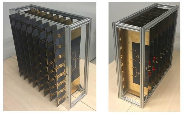
Figure 4
Simulated radiation pattern of the subarray
Figure 5
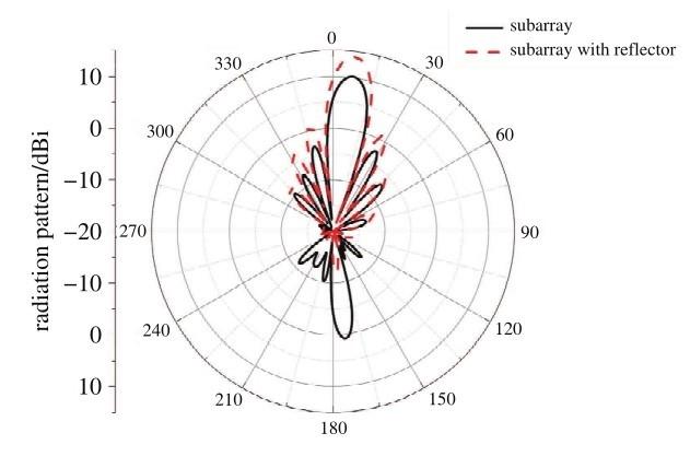
Figure 5
Photographs of the proposed subarray
Fig.6 shows photographs of the complete antenna array. The antenna array is supported by an aluminum frame. A mental reflector is set in front of the aluminum frame.
As shown in Figs. 5 and 6, every subarray has two ports, and the complete antenna array has 16 ports. Because the subarrays are the same, only some typical measurement results are illustrated in this paper.
Fig.7 shows the measured S-parameter results of the pro posed antenna array. For simplicity, only four ports, which are marked in Fig.6, are listed in Fig.7. Fig.7(a)illustrates S11 and S22 response in the desired band around 2. 6 GHz. The measured reflection coefficients are lower than−17 dB. Fig.7(b)illustrates the measured isolation between different ports. One can observe that S21 and S43 responses are lower than−10 dB in the desired band and the isolation between different subarrays, such as S41 and S31, is even lower than−20 dB. For practical applications, the isolation of the proposed antenna array is acceptable.
Figure 6
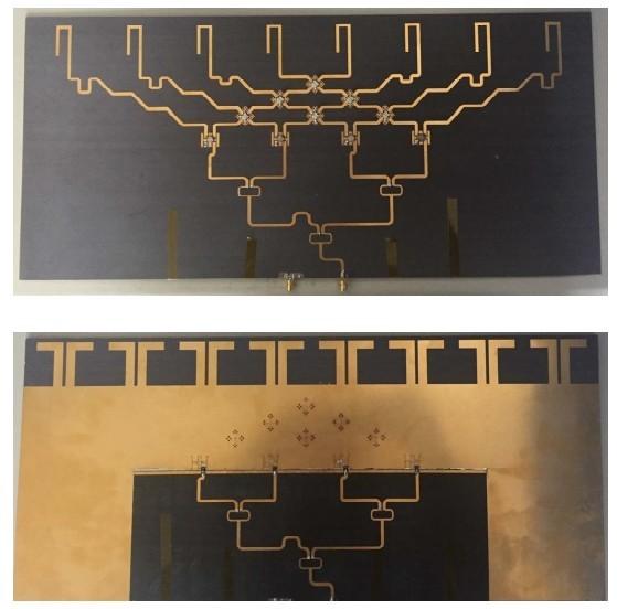
Figure 6
Photographs of the proposed antenna array
Figure 7
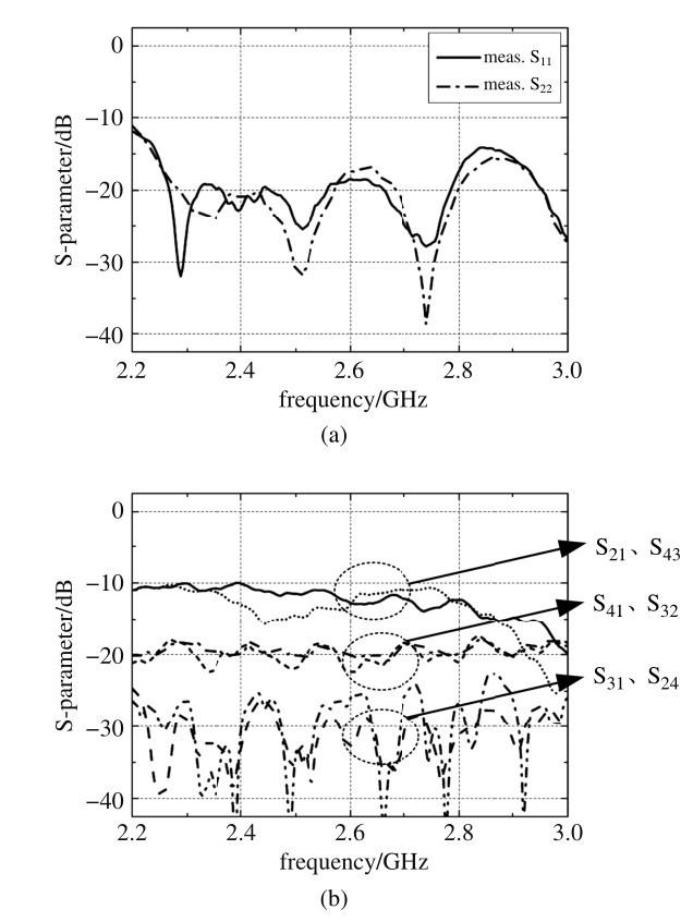
Figure 7
Measured S-parameters of the proposed antenna array: (a)S11 and S22 response in the desired band around 2. 6 GHz; (b)the measured isolation between different ports
Figure 8
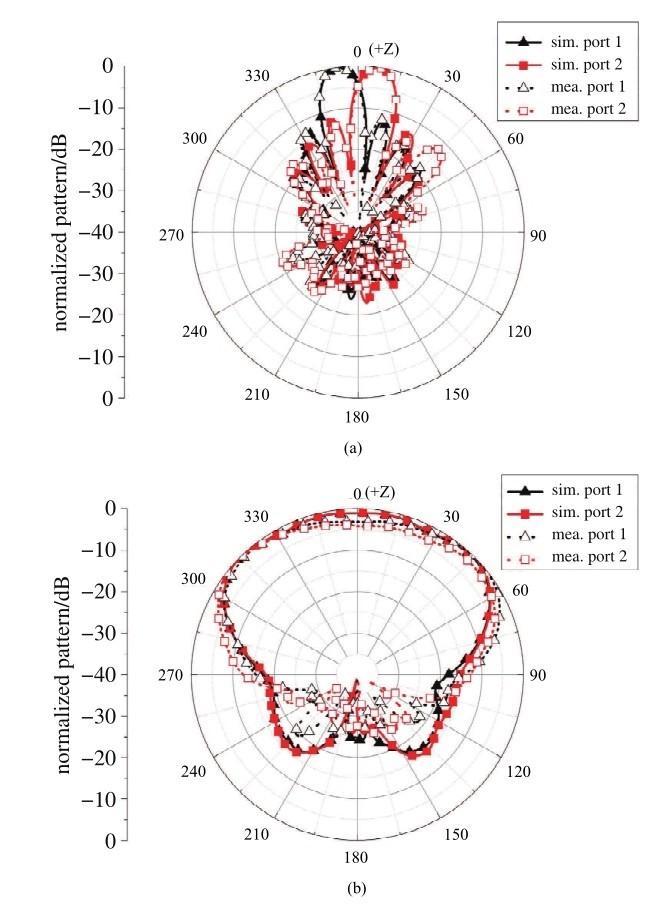
Figure 8
Normalized radiation patterns of the proposed antenna array at 2. 6 GHz: (a)E-plane patterns; (b)H-plane patterns
Because the full-wave simulation software cannot simulate the hybrid couplers and the crossovers, the simulated radiation patterns are obtained without the microstrip line feeding network. Fig.8 shows the normalized radiation patterns of the proposed antenna array in both E-plane and H-plane. In Fig.8(a), the E plane measurement shows that the proposed antenna array achieves two fan beams at ±7°, respectively. The measured peak gain of the proposed antenna array is 10.1 dBi. The difference between simulated and measured results in Fig.8 is due to the fabrication and measurement errors.
Ⅴ. CONCLUSION
In this paper, a 2D multiple fan-beam antenna array is proposed for operation at 2. 6 GHz to achieve beam mapping in the vertical dimension. The antenna is designed based on the VSF technique, which is proposed recently to solve the RF complexity issue in massive MIMO systems. The proposed antenna array uses only 16 ports to excite 64 printed dipole antennas. Compared with conventional massive MIMO systems, which need 64 ports, the proposed antenna array reduces RF complexity effectively and shows potential for practical applications.
Reference
Massive MIMO in real propagation environments: do all antennas contribute equally
[J].
Energy and spectral efficiency of very large multiuser MIMO systems
[J].
Achieving“massive MIMO”spectral efficiency with a not-so-large number of antennas
[J].
Large system analysis of sum capacity in the Gaussian MIMO broadcast channel
[J].
Massive MIMO and small cells: Improving energy efficiency by optimal soft-cell coordination
[C]//
Redcued-complexity transmit/receive-diversity systems
[J].
DFT-based hybrid antenna selection schemes for spatially correlated MIMO channels
[J].
Performance analysis of multiuser diverisity in MIMO systems with antenna selection
[J].
Spatial modulation for generalized MIMO: challenges,opportunities,and implementation
[J].
Design guidelines for spatial modulation
[J].
Electromagnetic lens-focusing antenna enabled massive MIMO: performance improvement and cost reduction
[J].
Low RF-complexity millimeter-wave beamspace-MIMO systems by beam selection
[J].
A dual-beam eight-element antenna array with compact CPWG crossover structure
[J].
Low RF-complexity massive MIMO systems based on vertical spatial filtering for urban macro cellular networks
[J].
