Journal of Communications and Information Networks, 2018, 3(2): 14-27 doi: 10.1007/s41650-018-0020-7
Research papers
Low-Cost Massive MIMO: Pilot Length and ADC Resolution
Dan Qiao,, Xi Yang,, Weiqiang Tan,, Chaokai Wen,, Shi Jin,
National Mobile Communications Research Laboratory, Southeast University, Nanjing 210096, China
作者简介 About authors
Dan Qiao was born in Jiangsu, China, in 1991 She received her B S degree and the M S degree from the School of Information Science and Engineering, Southeast University, Nanjing, China in 2014 and 2017 respectively Her main research interests include massive MIMO systems, and low resolution ADCs
, E-mail:qiaodancn@gmail.com.
Xi Yang received her B S degree and the M S degree from Southeast University, Nanjing, China in 2013 and 2016 respectively She is currently working toward her Ph D degree with the School of Information Science and Engineering, Southeast University Her main research interests include massive MIMO system prototyping, beam training and channel estimation in millimeter wave, and millimeter wave system prototyping
, E-mail:ouyangxi@seu.edu.cn.
Weiqiang Tan received his Ph D degree from the National Mobile Communications Research Laboratory, Southeast University, Nanjing, China, in 2017 He received his M S degree from Chengdu University of Information Technology, China, in 2013 From 2016 to 2017, he was a visiting Ph D student with the School of Electronics, Electrical Engineering and Computer Science, Queen’s University Belfast, United Kingdom He is currently with the School of Computer Science and Educational Software, Guangzhou University, China His research interests include massive MIMO system and Millimeter wave wireless communication
, E-mail:jinshi@seu.edu.cn.
Chaokai Wen (S’00-M’04) received his Ph D degree from the Institute of Communications Engineering, Tsing Hua University, Hsinchu, Taiwan, China, in 2004 He was with Industrial Technology Research Institute, Hsinchu, Taiwan, China and MediaTek Inc , Hsinchu, Taiwan, China, from 2004 to 2009 He is currently an Associate Professor with the Institute of Communications Engineering, Sun Yat-sen University, Kaohsiung, Taiwan, China His research interests center around the optimization in wireless multimedia networks
, E-mail:wqtan@gzhu.edu.cn.
Shi Jin(S’06-M’07)[corresponding author]received his B S degree in communications engineering from Guilin University of Electronic Technology, Guilin, China, in 1996;his M S degree from Nanjing University of Posts and Telecommunications, Nanjing, China, in 2003;and his Ph D degree in communications and information systems from Southeast University, Nanjing, in 2007 From June 2007 to October 2009, he was a Research Fellow with the Adastral Park Research Campus, University College London, London, U K He is currently with the faculty of the National Mobile Communications Research Laboratory, Southeast University His research interests include space-time wireless communications, random matrix theory, and information theory Dr Jin serves as an Associate Editor for the IEEE Transactions on Wireless Communications, the IEEE Communications Letters, and IET Communications He and his coauthors received the 2010 Young Author Best Paper Award by the IEEE Signal Processing Society and the 2011 IEEE Communications Society Stephen O Rice Prize Paper Award in the field of communication theory
, E-mail:ckwen@ieee.org.
Abstract
When designing an energy efficient massive multiple-input multiple-output (MIMO) system where each receiver antenna is equipped with a low-resolution analog-to-digital converter (ADC), the number of base station(BS)antennas and quantization bits are generally two mutually conflicting system parameters. In this paper, we investigate the joint optimization of the number of BS antennas and ADC resolution in quantized massive MIMO systems, assuming imperfect channel state information(CSI). A tractable approximate expression for the uplink sum spectral efficiency (SE) using maximal ratio combining(MRC)receivers is derived, based on which the pilot length which maximizes the sum SE is put forward. Considering the effect of ADCs, a realistic model of total power consumption is given subsequently. Capitalizing on it, we formulate the optimization problem of selecting the number of BS antennas and ADC resolution to maximize the sum SE under a total power consumption constraint. Our results show that more pilot symbols should be assigned for massive MIMO systems with low-resolution ADCs, especially for the receivers with one-bit quantizers. Moreover, the results show the trade-off between the number of BS antennas and quantization bits. Numerical results suggest that there exists an optimal ADC resolution in massive MIMO systems, while lower quantization bits may cause a substantial degradation of the SE performance and higher one will consume more power.
Keywords:massive MIMO
;
quantization
;
imperfect CSI
;
pilot length
;
spectral efficiency
;
power consumption
Dan Qiao. Low-Cost Massive MIMO: Pilot Length and ADC Resolution. [J], 2018, 3(2): 14-27 doi:10.1007/s41650-018-0020-7
Ⅰ. INTRODUCTION
With the development and popularization of intelligentterminals, wireless communications have witnessed an explosive growth in data traffic demands. This phe-nomenon will continue because of the increasingly rich in-ternet content, audio and video streaming and file sharing[1,2,3,4,5]. The power consumption of the communication technology in-dustry escalates to meet this increasing data rate demand, with the corresponding environmental concerns becoming key eco-nomical and societal problems[6,7,8]. This has stimulated both the academic and the industrial community to pursue the new research area of green cellular networks, whose goal is to develop innovative network architecture and technologies to improve the achievable energy efficiency (EE) of the entire wireless communication systems[9]. A significant body of researches have been done to improve the EE[10,11,12], among which the effort of dealing with the improved cost in massive multiple-input multiple-output (MIMO) systems has drawn more and more attention recently.
As a promising technology of the 5th generation (5G), massive MIMO can fully exploit spatial resources and allow for significant improvement in spectral and energy efficiency, which are crucial to meet the requirements of a data-centric world where spectrum and energy resources are increasingly precious[13,14,15,16]. It was shown in Ref. [13]that for a time division duplex(TDD)based cellular wireless system operating over a total bandwidth of 20 MHz and frequency re-use factor of 1, when the number of antennas at base station(BS)tends to be infinity, it can serve at most 42 user terminals with the mean net capacity per cell as high as 1 800 Mbit/s, which is nearly 24 times of that in a long term evolution-advanced system. The work in Ref. [14]further showed that to maintain the same uplink rates for finite number of BS antennas M, the transmitted power of each user was proportional to 1/M if the BS has perfect channel state information(CSI), and proportional to if CSI is estimated from uplink training. Different from Refs. [13,14]in which the TDD protocols are used so that the BS can make use of uplink estimates for both recep tion and downlink transmission, Refs. [17,18]investigated the frequency division duplex(FDD)protocols in massive MIMO systems, and proposed joint spatial division and multiplexing and beam division multiple access transmission schemes, re-spectively. A unified transmission strategy for both TDD and FDD massive MIMO systems was proposed in Ref. [19]. The author built a spatial basis expansion model(SBEM)to repre-sent the UL/DL channels, which greatly reduced the training overhead and feedback cost, as well as relieved the pilot con-tamination problem.
While massive MIMO improves the system performance dramatically, it also faces entirely new problems: the chal-lenge of mass data processing, expensive hardware cost and high total power consumption. A promising approach to solve these problems is to reduce the resolution of analog-to-digital converter(ADC)in receivers[20,21,22], which makes the low cost, low power consumption and low complexity deployment of massive MIMO systems possible. The result in Ref. [22]in-dicated that the system performance degradation due to the low-resolution ADCs could be compensated by increasing the number of antennas at BS. As the work Ref. [22]only considered the maximal ratio combining(MRC)scheme, the work Ref. [23]provided a supplement to it by employing the zero-forcing technique at the receivers, which corroborated the feasibility of installing finite precision ADCs in practi-cal massive MIMO systems. A general analytic framework which accounts for more realistic fading models was con-sidered in Ref. [24], where the achievable rate of massive MIMO systems with finite precision ADCs over Rician fading frequency-flat channels was investigated(of which Rayleigh fading is a special case). By evaluating the spectral effi-ciency(SE)of single carrier and OFDM transmission in mas-sive MIMO systems that use one-bit ADCs, Ref. [25]ad-vocated the wideband massive MIMO systems with one-bit ADCs. In Ref. [26], the authors presented an analysis of the effect of bandwidth and ADC resolution on achievable rate under a receiver power constraint, which also validated that the quantized MIMO architecture works well with low-resolution ADCs.
Although these studies suggest that a large number of BS antennas enable the use of low precision hardwares, an in-creased number of receiving antennas bring increased total power consumption[27]. Additionally, it is uncertain whether equipping extremely low precision ADCs will be acceptable in EE perspective. Therefore, a trade-off between the number of BS antennas and the resolution of ADCs, which has been studied in Refs. [26,28]for the millimeter wave and single an-tenna systems respectively, must be found to ensure an energy efficient massive MIMO system. We aim at finding the num-ber of BS antennas and ADC resolution to maximize the sum SE while maintaining the power consumption below a cer-tain threshold. To this end, an accurate modeling of the total power consumption is of significant importance[29]. As nor-mally done in related literature, the total power consumption is defined as the radiated transmit power combined with a con-stant quantity accounting for the circuit power consumption[6]. This model is formed without any consideration for the fact that the power consumed by digital processing and analog cir-cuits grows with the number of BS antennas and the number of user equipments(UEs), which will result in an infinite EE. While the circuit power consumption can be regarded as con-stant only in multi-user MIMO systems with small number of BS antennas and UEs, Ref. [30]proposed a new realistic power consumption model for massive MIMO systems that reveals how different system parameters affect the EE. The author in Ref. [31]further took into account the hardware im-pairments and formulated a corresponding power consump-tion model to analyze the hardware design for the efficient operation of massive MIMO systems.
In this paper, we investigate the pilot length and the tradeoff between the number of BS antennas and the number of quantization bits for quantized massive MIMO systems. We first derive a tight approximation of the uplink SE with the minimum mean-square error(MMSE)channel estimator followed by the MRC receivers. Capitalizing on the derived approximation, the pilot length which maximize the sum SE is put forward. Then we concentrate on the energy consumption of the system and a new refined model of the total power consumption accounting for the quantization distortions of ADCs is utilized. Based on the the derived SE and the power consumption model, we formulate the optimization problem as to maximize the uplink sum SE under a total power consumption constraint. Our result shows that an excessive number of pilot symbols is required in massive MIMO systems with lowresolution ADCs. Especially, the pilot length for the extreme case with one-bit quantizers is always greater than the number of users, revealing that increasing transmit power cannot unlimitedly improve the accuracy of channel estimate. The result also shows the trade-off between the number of BS antennas and the number of quantization bits, which allows us to further obtain insights on hardware design of massive MIMO networks. The numerical results suggest that the ADC resolution equal to about 5 bits is the optimal choice.
The remainder of this paper is organized as follows. In section Ⅱ, we introduce the system model for the uplink transmission of a massive MIMO system, and provide the definition and the corresponding approximation of the uplink SE with imperfect CSI. The pilot length which maximizes the sum SE is derived in section Ⅲ. In section Ⅳ, we first give a refined power consumption model, then focus on the problem of selecting the number of BS antennas and quantization bits to maximize the sum SE while restricting the power consumption below a threshold. In section V, we provide a set of numerical results to validate the theoretical analysis, while section Ⅵ summarizes the main conclusions of this paper.
Notations: Throughout the paper, boldfaced letters are used to represent vectors and matrices. The operator(·)H and(·)∗stand for the Hermitian and conjugate of a matrix, respectively. We let IN denotes an N×N identity matrix, and diag(A) denotes the diagonal matrix with the same diagonal elements as matrix . The notation indicates the expectation operator, whereas stands for the Euclidean norm. We use to denote a multi-variate circularlysymmetric complex Gaussian distribution.
Ⅱ. SYSTEM MODEL
Consider the uplink of a single-cell multi-user MIMO sys-tem formed by a base station(BS)equipped with an array of M antennas and serving N single antenna user terminals in the same time-frequency resource (see Fig.1). The hexag-onal cell is assumed to have radius of rc, and the users are distributed uniformly and randomly over it with the exclusion of a central disk of radius rh. We assume independent and identically distributed (i. i. d. ) Rayleigh block fading over T symbols, which means that the channels are considered static within each time-frequency coherent block and have indepen-dent realizations in different blocks.
Figure 1
Illustration of a multi-user MIMO scenario: a BS is equipped with an array of M antennas and simultaneously serves N randomly distributed single-antenna user terminals in the same time-frequency resource
Single-carrier, narrowband transmission is considered, and thus the channel matrix between BS and users are represented by an M×N matrix , where is the M×N matrix modeling small-scale fading coefficients between the users and BS, and is the N×N diagonal matrix representing the large-scale fading (both path loss and shadow fading)coefficients. The(m, n)element of G can be modeled as p , with hmn describing the instantaneous propagation channel from the nth user to the mth antenna of BS and βn being the large-scale fading component. We assume a Rayleigh small-scale fading distribution such that hmn is zero mean, circularly symmetric, complex Gaussian random variable with variance 1. Besides, βn is assumed to be constant across the antenna array[13].
Linear processing is used at a BS to perform uplink data detection. Under imperfect CSI assumption, the UEs send orthogonal pilot sequences of length τ symbols to the BS for channel estimation, which indicates that(T−τ)symbols are left to enable uplink data transmission. The entire uplink transmission process consists of the following three phases.
• First, the UEs send pilot sequences which are spatially orthogonal and τ symbols long. As seen from Fig.2, uplink pilot transmission takes place first and occupies τ symbols.
• Second, based on the received pilot sequences at the BS, channel estimation is performed for linear receiver processing. In this paper, we ignore the processing time needed for this phase.
• Third, all terminals send their uplink data to the BS using the remaining(T−τ)symbols, which is shown in Fig.2.
Figure 2
Illustration of the uplink transmission: uplink pilot signaling takes place first and occupies τ symbols; the subsequent(T−τ)symbols are used for uplink data transmission
A. Uplink Training and Data Transmission
In the uplink training phase, the UEs transmit a sequence of pilot signals which can be grouped into a matrix with each element being the pilot vector for the nth user and τ representing the number of training symbols. Assuming that each user terminal transmits the pilot symbol with equal transmit power pt, the signal of ith symbol at the receive antennas is written as
where gn denotes the nth column of the channel matrix , is the ith element of , and wi represents the additive white Gaussian noise(AWGN)vector with zero mean and unit element-wise variance written as .
In practical systems, an automatic gain control(AGC)variable gain amplifier is usually used before the ADC to adjust the dynamic range of the received signal . We assume the gain of AGC is set appropriately, and by adopting the additive quantization noise model, the output of the quantizer can be formulated as
where α=1−ρ with ρ being the inverse of the signal-toquantization-noise ratio, and is the additive Gaussian quan tization noise vector that is uncorrelated with . The covariance matrix of , which depends on the number of quantization bits b, is given approximately by
where . Note that the values of ρ can be ap-proximated by when b> 5, and for b 6 5, the values are associated with the number of quantization bits, which can be found in Ref. [22]. Following Eq. (3), we further express as
It can be seen from Eq. (4)that the covariance of is dependant on the pilot symbols ψni. In this paper we assume the pilot sequence ψn is the nth row of a discrete Fourier transform (DFT)matrix, which means that|ψni|2=1/τ. Consequently, we have , with
With representing the quantizer outputs of the ith symbol, when a block of pilot symbols Ψ is transmitted, the quantized signal of τ symbols can be grouped into an M×τ matrix . In addition, we let and such that the signal model after the ADC in matrix form becomes
The MMSE estimate of the channel G, from the received and quantized signal , between all UEs and all BS antennas is[32]
where . denote the channel estimation error, and after some simple calculation, the variance of elements of is
One important observation from Eq. (8)is that the variance of the channel estimation error is independent of the BS antenna index m. This means that for one specific UE, the variance of channel estimation error between this user and all the antennas at BS remains the same. Besides, it can be found that is monotonically decreasing with α and touches the minimum at α=1, which indicates that the accuracy of channel estimate can be enhanced by increasing the precision of the ADCs.
After the training phase comes the data transmission process, in which all N terminals send their data to the BS using the remaining(T−τ)symbols. Uplink data symbols transmitted by all users are collected in vector , where ? ? and pd denotes the average transmitted power of each terminal. The M×1 received signal at the BS is represented as
where is the AWGN vector with zero mean and unit element-wise variance[22,33,34,35]. Following Eq. (2), the received signals are quantized by ADCs and the quantization output is represented as
where denotes the additive Gaussian quantization noise vector.
As we have obtained the channel estimates, we are able to combine the received vectors to express separate transmitted symbols of each UE. Here we consider linear detection techniques to minimizing the computational complexity. Linear processing matrices for simple MRC are formed with the channel estimates as . The massive MIMO receiver applies the processing matrix to detect the transmitted signals as
According to Eq. (11), the estimated symbols sent by the nth user are calculated as
where and ei are the ith columns of and E, respectively. The last four terms in Eq. (12)account for different interference and noise sources, namely: intra-cell interference, channel estimation error, receiver noise, and quantizer noise, respectively.
B. Uplink SE with Imperfect CSI
Under the classical assumption of worst-case uncorrelated Gaussian noise[14], along with the fact that the variance of elements of receiver noise is 1 and the variance of elements of estimation error is , the uplink SE(in bits · s−1 · Hz−1)of the nth UE is obtained by
where
If MRC detection is applied with MMSE channel estimate in the quantized MIMO systems, we can approximate the uplink SE of the nth user as
where .
See appendix.
The SE expression of Eq. (14) in Theorem 1 is different from Ref. [22]due to the imperfect CSI which causes unavoidable interference between the users. In particular, Theorem 1 reveals the effect of the number of antennas M, number of quantization bits b, pilot length τ and transmit power pt, pd on the SE performance. To have a full and profound understanding of Theorem 1, we give some asymptotic results as follows.
For the special case of b→∞with fixed user transmitter power and number of BS antennas, the uplink SE of the nth user in Eq. (14)can be simplified as
As b grows without bound, we have α→1. The result is directly obtained by setting α=1 in Eq. (14).
Corollary 1 shows a precise agreement with the result derived in Ref. [32], where the achievable SE for the infinite precision case is given. The result also validates the accuracy of our derived approximation in Eq. (14), which embraces the results in Ref. [32]as a special case. We will discuss how different pilot lengths influence the system performance and the optimal resource allocation scheme in the following sections. With fixed ADC quantization bits b and the number of BS antennas M, when the training signal power equals the data transmit power and tends to be unlimited, i. e. , pd=pt→∞, the approximation in Eq. (14)reduces to
To better observe the relation between and pd, pt, we rewrite Eq. (14)as
where
SINR
with
We further calculate Eq. (18)by dividing pt pd from both the numerator and denominator to get
SINR
Obviously, when pd=pt→∞, we have
Substituting Eq. (21)into Eq. (17), we finally obtain the result in Eq. (16).
Corollary 2 indicates that when the transmit power of pilot and data signal tends to infinity, the approximate SE approaches a fixed value which is dependent of the pilot length τ and the quantization bits b. This observation reveals that increasing the transmit power in quantized massive MIMO systems will not eliminate the effects produced by the MMSE channel estimation.
Based on the expression in Eq. (14), we can investigate the optimization of pilot length τ and the joint optimization of quantization bits b and the number of antennas M to maximize the uplink SE, which will be carried out in the following sections.
Ⅲ. PILOT LENGTH
Under training-based schemes, the receiver usually requires the transmitter to send known training symbols to learn the channel. How training affects the capacity of a fading channel in MIMO systems has been studied in a number of works[36,37,38], since less training leads to improperly learned channel and too much training results in less time for data transmission. In particularly, Ref. [38]investigated the problem of given a multi-antenna wireless link with fixed transmit antennas, receive antennas, coherence interval and signal-tonoise ratio(SNR), how much of the coherence interval should be spent training. However, it did not take the quantization effect into consideration.
In this section, we consider the quantized MIMO systems and aim at finding the pilot length τ to maximize the uplink achievable SE. Although Ref. [39]showed that allocating different powers for the uplink training and data transmission phases can improve the system performance, in this paper we follow the methodology in Ref. [13]that the training and data powers are set to be equal, i. e. , pt = pd = p. Furthermore, we assume that all users suffer the same large-scale fading, i. e. , βn=β, ∀n. Under these assumptions, we define the optimization problem as follows
where the optimization variable τ is an integer variable, and is the sum SE with given in Eq. (14). The uplink SE of the nth user can be rewritten as
where
Thus the sum SE in Eq. (22)becomes
and the pilot sequence length τ satisfies
To find the optimal solution in Eq. (25), we first investigate the properties of . Through some basic calculations, the first and second derivatives of are given by
and
Since a, b and c are all positive, we have for τ> 0.Moreover, it is easily seen from Eq. (26)that is monotonically decreasing function of τ, with and . Therefore we draw the conclusion that is strictly concave in τ for τ> 0.In particular, first increases and then decreases in the interval(0, ∞).
Note that above we treat τ as a continuous variable in (0, ∞), while the truth is that the pilot length must be a positive integers in the interval[N, T]. Considering the constraint of both and N 6 τ 6 T, we have the following proposition.
Proposition 1 The pilot length τ∗that maximizes the uplink sum SE in Eq. (25)obeys the following properties.
• If , then τ∗ can be obtained by Newton’s method and then rounded to the nearest integer.
• If , the pilot length satisfies τ∗=N.
Based on the properties of , we know that is strictly concave in τ for τ > 0.Fig.3 shows the trend of the sum SE as a function of the pilot length τ. By using simple calculus we can verify that is less than 0, and if , we obtain that first increases and then decreases over the range N 6 τ 6 T. Under this condition, reaches a maximum value at τ∗ which satisfies , just as shown in the left part of Fig.3. Therefore the value of τ∗can be obtained by Newton’s method and then rounded to the nearest integer as described in Proposition 1. On the other side, when , is a monotonically decreasing function of τ in the interval[N, T], as shown in the right part of Fig.3. As a result, the pilot length τ∗equals N.
Figure 3
The different trends of sum SE over pilot lengths:(a);(b)
Proposition 1 shows that the pilot length τ∗is dependent on the value of . According to Eq. (26), relates to several system parameters, such as the number of BS antennas, the number of users, the transmit power, the number of quantization bits and so on. In other words, the pilot length τ∗ is varied along with the system parameters which will be validated by the simulation results.
Ⅳ. ADC RESOLUTIONS
Although the system SE performance loss due to equipping low resolution ADCs can be compensated by increasing the number of receiving antennas[22], the large number of BS antennas also leads to higher total power consumption. This has stimulated the design of energy efficient massive MIMO systems where a trade-off between ADC resolutions and a number of BS antennas must be found. In this section, we will investigate the quantization distortions of ADCs and number of BS antennas to maximize the system total SE while keeping the power consumption below a certain threshold.
A. Power Consumption Model
An accurate modeling of the system power consumption (including signal processing and antenna hardware)is of sig-nificant importance when optimizing b and M under a total power consumption constraint. Based on Refs. [30,31], we present a general power consumption model taking the reso-lution of ADCs into account. Total power consumption of the BS in the uplink can be expressed as
where PTX accounts for the average uplink power amplifier (PA)power(in Watt)defined as the power consumed by the PAs, and PCP is the circuit power consumption.
In many related works, PCP is defined as a constant value including the fixed power consumption needed for baseband processors and backhaul infrastructure[6]. In fact, this model is not accurate enough to be as close as hardware reality, for it neglects the fact that each antenna at the BS requires dedi-cated circuits with non-zero power consumption, and the sig-nal processing tends to be increasingly complex when more and more antennas at BS are added. Hence, the circuit power consumption can not be simply modeled as a constant quan-tity. A more accurate and functional modeling of PCP is of primary importance when an energy-efficient massive MIMO system is designed by optimizing the number of antennas(M) and number of quantization bits(b). In the following, we aim at presenting an appropriate model of PCP(b, M)as a function of the two principal design parameters which are also our op-timization objective.
The circuit power consumption PCP consists of the power consumed by different analog components and digital sig-nal processing[6]. For a multi-user MIMO system, the circuit power consumption model is defined as[30]
where PFIX accounts for the fixed power as mentioned before, PTC represents the power consumption of the transceiver chains, PCE is the power consumed by channel estimation, and PLP is the power consumed by linear processing at the BS. Next we will give each term in Eq. (29)a realistic and accurate analysis of their relation (linearly or non-linearly) with the main system parameters(b, M).
1) Transceiver Chains: The power consumption of the transceiver chains PTC comprises of a set of typical transmitters and receivers, and it can be defined as
where PBS denotes the power consumption needed to run the circuit components attached to each antenna at the BS, such as analog-to-digital/digital-to-analog converters, mixers, filters and so on. PSYN accounts for the power required by the local oscillator, and PUE represents the power consumed by all circuit components of each single-antenna UE, such as amplifiers, oscillator, mixer, and filters.
For the power consumption of circuit components PBS, one important part is the power required by the converters, among which the ADCs are responsible for a major portion. Each antenna generally demands two separate ADCs(in-phase and quadrature branches)to digitalize the analog signal. We define the power consumption of each ADC as PADC, and the remaining portion of PBS as , the total power required at BS is quantified as
where PADC can be further calculated as
where is constant coefficient with a typical value as [W/conversion step], andϕ> 0 is also set constant with a typical value asϕ∈[1, 2]. The choice of andϕ depends on the figure-of-merit(FoM)of ADCs where smaller is paired with largerϕand vice versa. This power consumption model of the ADC encompasses varying architecture and implementations of ADCs which are described in Refs. [40,41,42].
2)Channel Estimation: Channel estimation in the uplink is performed locally at the BS with computational efficiency of current microprocessors known as[bit operations/J](also in flops/Watt). The pilot-based channel estimation is carried out once per block. In the uplink of multi-user MIMO systems, the BS receives the pilot signal as an M×τ matrix and then estimate each user’s channel by multiplying with the corresponding pilots of all UEs Ψ. From numerical linear algebra computations, this is a standard operation and consume
where L is the computational efficiency at the BS, and BW is the bandwidth the system operates over.
3)Linear Processing: The received vector of information symbols at the BS are processed by maximal ratio combining as . The amount of power required for signal processing is also related to the number of quantization bits used by the ADCs. We calculate the number of bit operations required for linear processing, and divide it by the computational efficiency to get
To sum up, we combine Eqs. (30), (33) and (34) into Eq. (29)to obtain the circuit power consumption as
Recall that the total power consumption of the BS in the uplink of a multi-user MIMO system is P=PTX+PCP, which can be rewritten in the more concrete form
where , , , and . The first term in accounts for the transmission power consumption with η being the efficiency of the power amplifier. represents the fixed power consumption required for site-cooling, control signaling, and so on. , denote the power consumption per antenna of the BS and UE respectively which are independent of the number of quantization bits b.
B. Problem Statement and Solving
Despite the fact that equipping highly economical ADCs with low resolution in practical massive MIMO systems is feasible, it is not sure whether such low ADC precision is acceptable in terms of SE and power consumption performance. This subsection aims at analyzing the number of BS antennas M and ADC resolution b that maximizes the uplink sum SE, defined as with given in Theorem 1, subject to a total power consumption constraint. An SE-optimal multi-user MIMO setup is achieved by solving the following optimization problem:
where γ accounts for the maximum value of the system total power consumption, and the optimization variables b and M are non-negative integers whose set is denoted by .
To find the optimal solution of Eq. (37), we first provide the properties of the sum SE RSUM(b, M)and the total power consumption P(b, M)in the following lemma. Both P(b, M)and RSUM(b, M)are monotonically increasing functions of b. In addition, P(b, M)increases linearly with M while RSUM(b, M)increases nonlinearly with M. By using some basic calculations, we get that
and we have∂P(b, M)/∂b> 0, which indicates that P(b, M) increases monotonically with b. Moreover, we rewrite the total power consumption as , thus it can be deduced that P(b, M)is linearly increasing functions of M. Note that here we treat b and M as continuous variables, but the conclusion applied to the situation when b and M are nonnegative integers. With similar procedures, the properties of RSUM(b, M)are easy to be found.
Assuming that{b∗, M∗}is the optimal solution to Eq. (37), and it satisfies P(b∗, M∗)< γ. From Lemma 1, we know that P(b, M)increases monotonically with b, therefore there exists a value b1> b∗ such that P(b1, M∗)=γ. Recall that RSUM(b, M)is also a monotonically increasing function of b which means RSUM(b1, M∗)> RSUM(b∗, M∗). This is a contradiction to the presumption of P(b∗, M∗)< γ. Thus if the optimization problem is feasible, the maximum RSUM can only be found when P(b, M)=γ. As a result, the optimal values of b and M satisfy
To solve the optimization problem in Eq. (37), we can conduct an exhaustive search algorithm where b and M are both non-negative integers. Notice that the optimal solution is found for M being a decreasing function of b (according to Eq. (39)), which indicates that the largest possible M is obtained when b=1. This gives us a finite set of M as M∈{1, 2, …, bM(1)c}to conduct the exhaustive search over, and for each M we can solve P(b, M)=γ to get the corresponding value of b. To this end we present the following definition and proposition.
The Lambert-W function (also called the omega function or product logarithm)is the branches of the inverse relation of the function f(w)=w · ew where ew is the exponential function and w is any complex number. For any complex value z, there is
When the number of BS antennas M is fixed, the corresponding b, which satisfies P(b, M)=γ, is calculated as
where
Consider the equation with x being the variable px=ax+c, where p> 0 and a=0.To solve x from the equation, we first substitute−t=x+c/a, and the equation can be transformed into
given
which yields the final solution
Rewrite P(b, M)=γ as
and after some basic simplification, the above equation can be converted to
Let p=2ϕ, , , and we obtain
As b is constrained to be non-negative integer, we finally have .
From Proposition 2, we know that when the total power consumption P(b, M)is fixed, the optimal solution is found for b being a decreasing function of M. Thus, the largest feasible b is found when the BS antennas M equals to 1, which means the possible interval for b is b∈{1, 2, …, b(1)}. This gives us a different way to conduct the exhaustive search. Moreover, Proposition 2 also indicates that the quantization bits which maximize the sum SE are in dependent with the number of users N. When N increases, the corresponding b gets smaller, which implies that the low-resolution quantizers can be adopted in massive MIMO systems where N takes relatively bigger values. This property is reasonable because the maximum sum SE can only be achieved when P(b, M)=γ as explained before. Recall the expression of P(b, M)in Eq. (36), and it is easily found that N only linearly affects the last term of Eq. (36), which means the increasing N would result in the decreasing b to maintain the constant value of γ.
Ⅴ. NUMERICAL RESULTS
This section conducts numerical simulations to validate the analytical results obtained in the previous sections. We consider a hexagonal cell with radius rc, and the users are distributed randomly and uniformly over the cell, with the exclusion of a central disk radius rh meters. The large-scale fading of the nth user consists of path loss and shadow fading which can be modeled as βn=zn/(rn/rh)κ, where zn is a log-normal variable with standard deviation σshadow, rn is the distance between the nth user and BS, and κ is the path loss exponent. It should be pointed out that βn is constant across the antenna array and the expectation is taken over the fastfading coefficients. In the following simulations, we set the number of single-antenna users N=10, the coherence time of the channel T =196 in symbols, the radius of the hexagonal cell rc=1 000 m, and the exclusion of a central disk radius rh=100 meters. In addition, we assume that the power of training and data transmission phases are fixed, i. e. , pt=pd. The rest of the selected values of the main parameters are listed in Tab.1.
In this subsection, we evaluate the uplink sum SE of a quantized MIMO system with imperfect CSI and validate the accuracy of our proposed approximation in Theorem 1. Additionally, we analyze the pilot length which maximizes the uplink sum SE.
Fig.4 shows the sum SE RSUM as a function of the number of BS antennas M, where we set pt = pd =1 dB, and τ=10.We compare the simulated SE in Eq. (13)with its corresponding analytical approximation in Eq. (14)for three different quantization bits b=1, 2, and∞, respectively. It can be observed from the figure that there is a precise agreement between the simulation results and our theoretical results, which validates our analysis in Theorem 1. For an MRC receiver, as M increases, the sum SE grows obvious for three kinds of ADC resolution. Furthermore, we can see that the gap between high and low quantization bits decreases with b, which implies that adopting low-resolution ADCs(e. g. , 1-2 bits)is a promising solution in massive MIMO systems and the system performance loss can be compensated by increasing the number of BS antennas. For example, in order to achieve the sum SE of 4. 143 bit·s−1·Hz−1, systems with perfect quantization (b=∞)require about 150 antennas at BS while the BS antennas in system with low-resolution ADCs(e. g. , 1 bit)need to reach 350.The trade-off between M and b has been studied in the previous section and will be discussed in later simulations.
Figure 4
Uplink sum SE[bit·s−1·Hz−1]versus the number of BS antennas M,for b=1,2,∞,τ=10 and pt=pd=1 dB
To better understand the effect of ADC resolution on the system SE performance, Fig.5 shows the sum SE with respect to the quantization bits b. We observe from the figure that the sum SE increases with the number of quantization bits and converges to a fixed value obtained in Eq. (15), which agrees with the result derived in Ref. [32]for the infinite precision case. This conclusion is reasonable because α →1, which means b→∞, indicates that the quantization error brought by ADC can be neglected. Moreover, the growth rate slows down with the increase of b so that when the quantization bits reach about 8 bits, the SE performance of the quantized MIMO system is close to the traditional MIMO systems with perfect quantization.
Figure 5
Uplink sum SE[bit·s−1·Hz−1]versus the number of quantization bits b,for M=200,400,τ=10 and pt=pd=1 dB
B. Pilot Length and ADC Resolution
First, we give the sum SE with respect to the pilot length τ under different transmit power and quantization bits in Fig.6, where we assume that all users have the same large-scale fading coefficient β =1. Considering the tightness between the analytical approximations and the simulation result, we use the approximation in Eq. (14) for the following numerical analysis. From Fig.6, we can observe that when the transmit power p=−10 dB, the sum SE increases first and then decreases for all three different values of quantization bits. Under this setting, , and the pilot length that maximizes the sum SE τ∗> 10, which is in accordance with the first case in Proposition 1. However, when the transmit power p=10 dB, it is seen in the figure that for b> 1. The sum SE is a monotonically decreasing function of the pilot length τ. This observation is also understandable because this means , which leads to the pilot length τ∗that maximizes the sum SE being equal to N=10.In both cases, it is important to notice that τ∗ increases with decreasing b, which implies that longer training length is needed in low-resolution massive MIMO systems in order to improve the accuracy of channel estimation.
Figure 6
Uplink sum SE per cell versus the pilot length τ,where M=100 and N=10
The pilot length τ∗that maximizes the sum SE for different b and pd is given in Tab.2. We note that the pilot length τ∗varies with b and pd, and basically τ∗decreases with increasing b and pd, which agrees with our argument in Proposition 1 and the simulated result in Fig.6. Another interesting observation is that τ∗ for b=1 is quite different from the others. Although τ∗decreases when pd is increasing, it converges to 19 instead of 10(the number of users). This result indicates that unlike the infinite precision cases[36], increasing the transmit power cannot make the pilot length converge to the number of users for the extreme case with one-bit quantizers. In other words, the accuracy of the channel estimation will not improve unlimitedly even in the high SNR regime.
Table 2
Table 2 The pilot length τ∗for different transmit power pd and quantization bits b
Next we study the effect of several system parameters, especially the number of BS antennas and the quantization bits, on the total power consumption in Eq. (36). The ADCs are responsible for a large part of the power consumption and distortion noise. Plus, the computational complexity of baseband operations is proportional to the number of quantization bits. Thus Fig.7 gives the total power consumption as a function of b. As stated in Lemma 1, Fig.7 shows that P(b, M)increases monotonically with the quantization bits which are reasonable as a higher level of hardware quality leads to higher power consumption. Another interesting observation is that when the number of BS antennas becomes larger, the increase of total power consumption with quantization bits accelerates. The relation between M and b under fixed total power consumption is plotted in Fig.8 and it can be seen that M decreases with b which is in accordance with Eq. (39).
Figure 7
The total power consumption versus the number of quantization bits b,for M=50,200,400
Fig.9 depicts a 3-D graph of uplink sum SE RSUM in terms of b and M. We see that RSUM is monotonically increasing with b and also increasing with M. For a maximum power consumption γ, we plot the curves where P(b, M)=γ with γ={60, 64, 68}respectively. The corresponding M and b that maximize the sum SE are represented with triangle points. As proofed before, the maximum RSUM is found when P(b, M)=γ. It is seen from the figure that for a maximum power consumption of γ={60, 64, 68}, the maximum sum SE is achieved at M={159, 200, 235}and b={5, 5, 5}, which is clearly a massive MIMO with low-resolution ADCs setup.
Figure 9
Uplink sum SE as a function of M and b(3-D graph).The green,magenta,and blue lines represent the curves where P(b,M)=γ with γ ={60,64,68}. The triangle points are the corresponding M and b that maximize the sum SE
Once we have the value of M∗ and b∗ for a given γ, we can also obtain the EE(in bit/J), which is defined as the ratio between the average sum SE(in bit/s)RSUM(b∗, M∗)and the average total power consumption γ(in J/s). Fig.10 shows the EE as a function of the power consumption constraint γ. It can be seen that the EE first increases and then decreases as the maximum power consumption grows from 60 to 80.When the pilot length equals 10 and 30, the maximum EE is achieved at γ∗={67, 69}, which corresponds to M∗={226, 245}and b∗={5, 5}respectively. This observation indicates that we should choose the appropriate γ to maximize EE, which gives us further insight on how to design an energy efficient massive MIMO system.
Ⅵ. CONCLUSION
This paper analyzed the pilot length and how to select the number of antennas at BS and the ADC resolution to maximize the sum SE while keeping the total power consumption under a threshold in quantized massive MIMO systems. We first derived a tight approximation expression of the up link sum SE for MRC receivers with MMSE channel estimates, capitalizing on which the pilot length which maximize the sum SE is put forward. Subsequently, we used a realistic model of total power consumption which clearly describes the effect of several system parameters(such as M and b)on the power consumption. Based on it, we formulated an optimization problem and pointed out how to find the value of M and b. Our result shows that a longer pilot length is required in massive MIMO systems with low-resolution ADCs. In particular, for the extreme case with one-bit quantizers, the efficient way to obtain the maximum SE is to assign more training time instead of increasing the transmit power. Numerical results show that the ADC resolution corresponding to about 5 bits is a better choice considering the significance of deploying lowcost massive MIMO systems.
Figure 10
Energy efficiency as a function of total pow consumption constraint γ for the pilot length τ={10,30}
APPENDIX
Although the true distribution of can not be determined due to the quantization, we approximate it as Gaussian as the worst-case by using the result of Eqs. (7)and(8)and replacing with an auxiliary random vector wn according to
where σn is the variance of the channel estimate . According to the orthogonality principle, it is described as
Applying[32, Lemma 1], we begin by approximating Rn with
where
According to Ref. [22], the expectation of squared norm terms is
and the expectation of squared norm terms is
The random variable is gamma-distributed with shape M and scale βn and can be denoted by . Then, we obtain
Subsequently, we compute the last term in Eq. (52)as follows
Index,Global mobile data traffic forecast update 2014-2019 white paper
1
2015
... With the development and popularization of intelligentterminals, wireless communications have witnessed an explosive growth in data traffic demands. This phe-nomenon will continue because of the increasingly rich in-ternet content, audio and video streaming and file sharing[1,2,3,4,5]. The power consumption of the communication technology in-dustry escalates to meet this increasing data rate demand, with the corresponding environmental concerns becoming key eco-nomical and societal problems[6,7,8]. This has stimulated both the academic and the industrial community to pursue the new research area of green cellular networks, whose goal is to develop innovative network architecture and technologies to improve the achievable energy efficiency (EE) of the entire wireless communication systems[9]. A significant body of researches have been done to improve the EE[10,11,12], among which the effort of dealing with the improved cost in massive multiple-input multiple-output (MIMO) systems has drawn more and more attention recently. ...
On secrecy performance of MISO SWIPT systems with TAS and imperfect CSI
1
2016
... With the development and popularization of intelligentterminals, wireless communications have witnessed an explosive growth in data traffic demands. This phe-nomenon will continue because of the increasingly rich in-ternet content, audio and video streaming and file sharing[1,2,3,4,5]. The power consumption of the communication technology in-dustry escalates to meet this increasing data rate demand, with the corresponding environmental concerns becoming key eco-nomical and societal problems[6,7,8]. This has stimulated both the academic and the industrial community to pursue the new research area of green cellular networks, whose goal is to develop innovative network architecture and technologies to improve the achievable energy efficiency (EE) of the entire wireless communication systems[9]. A significant body of researches have been done to improve the EE[10,11,12], among which the effort of dealing with the improved cost in massive multiple-input multiple-output (MIMO) systems has drawn more and more attention recently. ...
Spectral efficiency of DFT based processing hybrid architectures in massive MIMO
1
2017
... With the development and popularization of intelligentterminals, wireless communications have witnessed an explosive growth in data traffic demands. This phe-nomenon will continue because of the increasingly rich in-ternet content, audio and video streaming and file sharing[1,2,3,4,5]. The power consumption of the communication technology in-dustry escalates to meet this increasing data rate demand, with the corresponding environmental concerns becoming key eco-nomical and societal problems[6,7,8]. This has stimulated both the academic and the industrial community to pursue the new research area of green cellular networks, whose goal is to develop innovative network architecture and technologies to improve the achievable energy efficiency (EE) of the entire wireless communication systems[9]. A significant body of researches have been done to improve the EE[10,11,12], among which the effort of dealing with the improved cost in massive multiple-input multiple-output (MIMO) systems has drawn more and more attention recently. ...
User-centric networking for dense CRANS: High-SNR capacity analysis and antenna selection
1
2017
... With the development and popularization of intelligentterminals, wireless communications have witnessed an explosive growth in data traffic demands. This phe-nomenon will continue because of the increasingly rich in-ternet content, audio and video streaming and file sharing[1,2,3,4,5]. The power consumption of the communication technology in-dustry escalates to meet this increasing data rate demand, with the corresponding environmental concerns becoming key eco-nomical and societal problems[6,7,8]. This has stimulated both the academic and the industrial community to pursue the new research area of green cellular networks, whose goal is to develop innovative network architecture and technologies to improve the achievable energy efficiency (EE) of the entire wireless communication systems[9]. A significant body of researches have been done to improve the EE[10,11,12], among which the effort of dealing with the improved cost in massive multiple-input multiple-output (MIMO) systems has drawn more and more attention recently. ...
Spectral efficiency and power allocation for mixed-ADC massive MIMO system
1
2018
... With the development and popularization of intelligentterminals, wireless communications have witnessed an explosive growth in data traffic demands. This phe-nomenon will continue because of the increasingly rich in-ternet content, audio and video streaming and file sharing[1,2,3,4,5]. The power consumption of the communication technology in-dustry escalates to meet this increasing data rate demand, with the corresponding environmental concerns becoming key eco-nomical and societal problems[6,7,8]. This has stimulated both the academic and the industrial community to pursue the new research area of green cellular networks, whose goal is to develop innovative network architecture and technologies to improve the achievable energy efficiency (EE) of the entire wireless communication systems[9]. A significant body of researches have been done to improve the EE[10,11,12], among which the effort of dealing with the improved cost in massive multiple-input multiple-output (MIMO) systems has drawn more and more attention recently. ...
Energy efficiency analysis of the reference systems,areas of improvements and target breakdown
4
2016
... With the development and popularization of intelligentterminals, wireless communications have witnessed an explosive growth in data traffic demands. This phe-nomenon will continue because of the increasingly rich in-ternet content, audio and video streaming and file sharing[1,2,3,4,5]. The power consumption of the communication technology in-dustry escalates to meet this increasing data rate demand, with the corresponding environmental concerns becoming key eco-nomical and societal problems[6,7,8]. This has stimulated both the academic and the industrial community to pursue the new research area of green cellular networks, whose goal is to develop innovative network architecture and technologies to improve the achievable energy efficiency (EE) of the entire wireless communication systems[9]. A significant body of researches have been done to improve the EE[10,11,12], among which the effort of dealing with the improved cost in massive multiple-input multiple-output (MIMO) systems has drawn more and more attention recently. ...
... Although these studies suggest that a large number of BS antennas enable the use of low precision hardwares, an in-creased number of receiving antennas bring increased total power consumption[27]. Additionally, it is uncertain whether equipping extremely low precision ADCs will be acceptable in EE perspective. Therefore, a trade-off between the number of BS antennas and the resolution of ADCs, which has been studied in Refs. [26,28]for the millimeter wave and single an-tenna systems respectively, must be found to ensure an energy efficient massive MIMO system. We aim at finding the num-ber of BS antennas and ADC resolution to maximize the sum SE while maintaining the power consumption below a cer-tain threshold. To this end, an accurate modeling of the total power consumption is of significant importance[29]. As nor-mally done in related literature, the total power consumption is defined as the radiated transmit power combined with a con-stant quantity accounting for the circuit power consumption[6]. This model is formed without any consideration for the fact that the power consumed by digital processing and analog cir-cuits grows with the number of BS antennas and the number of user equipments(UEs), which will result in an infinite EE. While the circuit power consumption can be regarded as con-stant only in multi-user MIMO systems with small number of BS antennas and UEs, Ref. [30]proposed a new realistic power consumption model for massive MIMO systems that reveals how different system parameters affect the EE. The author in Ref. [31]further took into account the hardware im-pairments and formulated a corresponding power consump-tion model to analyze the hardware design for the efficient operation of massive MIMO systems. ...
... In many related works, PCP is defined as a constant value including the fixed power consumption needed for baseband processors and backhaul infrastructure[6]. In fact, this model is not accurate enough to be as close as hardware reality, for it neglects the fact that each antenna at the BS requires dedi-cated circuits with non-zero power consumption, and the sig-nal processing tends to be increasingly complex when more and more antennas at BS are added. Hence, the circuit power consumption can not be simply modeled as a constant quan-tity. A more accurate and functional modeling of PCP is of primary importance when an energy-efficient massive MIMO system is designed by optimizing the number of antennas(M) and number of quantization bits(b). In the following, we aim at presenting an appropriate model of PCP(b, M)as a function of the two principal design parameters which are also our op-timization objective. ...
... The circuit power consumption PCP consists of the power consumed by different analog components and digital sig-nal processing[6]. For a multi-user MIMO system, the circuit power consumption model is defined as[30] ...
On the performance of three dimensional antenna arrays in millimeter wave propagation environments
1
2018
... With the development and popularization of intelligentterminals, wireless communications have witnessed an explosive growth in data traffic demands. This phe-nomenon will continue because of the increasingly rich in-ternet content, audio and video streaming and file sharing[1,2,3,4,5]. The power consumption of the communication technology in-dustry escalates to meet this increasing data rate demand, with the corresponding environmental concerns becoming key eco-nomical and societal problems[6,7,8]. This has stimulated both the academic and the industrial community to pursue the new research area of green cellular networks, whose goal is to develop innovative network architecture and technologies to improve the achievable energy efficiency (EE) of the entire wireless communication systems[9]. A significant body of researches have been done to improve the EE[10,11,12], among which the effort of dealing with the improved cost in massive multiple-input multiple-output (MIMO) systems has drawn more and more attention recently. ...
Spectral efficiency of multi-user millimeter wave systems under single path with uniform rectangular arrays
1
2017
... With the development and popularization of intelligentterminals, wireless communications have witnessed an explosive growth in data traffic demands. This phe-nomenon will continue because of the increasingly rich in-ternet content, audio and video streaming and file sharing[1,2,3,4,5]. The power consumption of the communication technology in-dustry escalates to meet this increasing data rate demand, with the corresponding environmental concerns becoming key eco-nomical and societal problems[6,7,8]. This has stimulated both the academic and the industrial community to pursue the new research area of green cellular networks, whose goal is to develop innovative network architecture and technologies to improve the achievable energy efficiency (EE) of the entire wireless communication systems[9]. A significant body of researches have been done to improve the EE[10,11,12], among which the effort of dealing with the improved cost in massive multiple-input multiple-output (MIMO) systems has drawn more and more attention recently. ...
Fundamental trade-offs on green wireless networks
1
2011
... With the development and popularization of intelligentterminals, wireless communications have witnessed an explosive growth in data traffic demands. This phe-nomenon will continue because of the increasingly rich in-ternet content, audio and video streaming and file sharing[1,2,3,4,5]. The power consumption of the communication technology in-dustry escalates to meet this increasing data rate demand, with the corresponding environmental concerns becoming key eco-nomical and societal problems[6,7,8]. This has stimulated both the academic and the industrial community to pursue the new research area of green cellular networks, whose goal is to develop innovative network architecture and technologies to improve the achievable energy efficiency (EE) of the entire wireless communication systems[9]. A significant body of researches have been done to improve the EE[10,11,12], among which the effort of dealing with the improved cost in massive multiple-input multiple-output (MIMO) systems has drawn more and more attention recently. ...
A survey of energy-efficient wireless communications
1
2013
... With the development and popularization of intelligentterminals, wireless communications have witnessed an explosive growth in data traffic demands. This phe-nomenon will continue because of the increasingly rich in-ternet content, audio and video streaming and file sharing[1,2,3,4,5]. The power consumption of the communication technology in-dustry escalates to meet this increasing data rate demand, with the corresponding environmental concerns becoming key eco-nomical and societal problems[6,7,8]. This has stimulated both the academic and the industrial community to pursue the new research area of green cellular networks, whose goal is to develop innovative network architecture and technologies to improve the achievable energy efficiency (EE) of the entire wireless communication systems[9]. A significant body of researches have been done to improve the EE[10,11,12], among which the effort of dealing with the improved cost in massive multiple-input multiple-output (MIMO) systems has drawn more and more attention recently. ...
Energy efficiency of LTE networks under traffic loads of 2020
1
2013
... With the development and popularization of intelligentterminals, wireless communications have witnessed an explosive growth in data traffic demands. This phe-nomenon will continue because of the increasingly rich in-ternet content, audio and video streaming and file sharing[1,2,3,4,5]. The power consumption of the communication technology in-dustry escalates to meet this increasing data rate demand, with the corresponding environmental concerns becoming key eco-nomical and societal problems[6,7,8]. This has stimulated both the academic and the industrial community to pursue the new research area of green cellular networks, whose goal is to develop innovative network architecture and technologies to improve the achievable energy efficiency (EE) of the entire wireless communication systems[9]. A significant body of researches have been done to improve the EE[10,11,12], among which the effort of dealing with the improved cost in massive multiple-input multiple-output (MIMO) systems has drawn more and more attention recently. ...
Spectral and energy efficiency of massive MIMO for hybrid architectures based on phase shifters
1
2018
... With the development and popularization of intelligentterminals, wireless communications have witnessed an explosive growth in data traffic demands. This phe-nomenon will continue because of the increasingly rich in-ternet content, audio and video streaming and file sharing[1,2,3,4,5]. The power consumption of the communication technology in-dustry escalates to meet this increasing data rate demand, with the corresponding environmental concerns becoming key eco-nomical and societal problems[6,7,8]. This has stimulated both the academic and the industrial community to pursue the new research area of green cellular networks, whose goal is to develop innovative network architecture and technologies to improve the achievable energy efficiency (EE) of the entire wireless communication systems[9]. A significant body of researches have been done to improve the EE[10,11,12], among which the effort of dealing with the improved cost in massive multiple-input multiple-output (MIMO) systems has drawn more and more attention recently. ...
Noncooperative cellular wireless with unlimited numbers of base station antennas
5
2010
... As a promising technology of the 5th generation (5G), massive MIMO can fully exploit spatial resources and allow for significant improvement in spectral and energy efficiency, which are crucial to meet the requirements of a data-centric world where spectrum and energy resources are increasingly precious[13,14,15,16]. It was shown in Ref. [13]that for a time division duplex(TDD)based cellular wireless system operating over a total bandwidth of 20 MHz and frequency re-use factor of 1, when the number of antennas at base station(BS)tends to be infinity, it can serve at most 42 user terminals with the mean net capacity per cell as high as 1 800 Mbit/s, which is nearly 24 times of that in a long term evolution-advanced system. The work in Ref. [14]further showed that to maintain the same uplink rates for finite number of BS antennas M, the transmitted power of each user was proportional to 1/M if the BS has perfect channel state information(CSI), and proportional to if CSI is estimated from uplink training. Different from Refs. [13,14]in which the TDD protocols are used so that the BS can make use of uplink estimates for both recep tion and downlink transmission, Refs. [17,18]investigated the frequency division duplex(FDD)protocols in massive MIMO systems, and proposed joint spatial division and multiplexing and beam division multiple access transmission schemes, re-spectively. A unified transmission strategy for both TDD and FDD massive MIMO systems was proposed in Ref. [19]. The author built a spatial basis expansion model(SBEM)to repre-sent the UL/DL channels, which greatly reduced the training overhead and feedback cost, as well as relieved the pilot con-tamination problem. ...
... . It was shown in Ref. [13]that for a time division duplex(TDD)based cellular wireless system operating over a total bandwidth of 20 MHz and frequency re-use factor of 1, when the number of antennas at base station(BS)tends to be infinity, it can serve at most 42 user terminals with the mean net capacity per cell as high as 1 800 Mbit/s, which is nearly 24 times of that in a long term evolution-advanced system. The work in Ref. [14]further showed that to maintain the same uplink rates for finite number of BS antennas M, the transmitted power of each user was proportional to 1/M if the BS has perfect channel state information(CSI), and proportional to if CSI is estimated from uplink training. Different from Refs. [13,14]in which the TDD protocols are used so that the BS can make use of uplink estimates for both recep tion and downlink transmission, Refs. [17,18]investigated the frequency division duplex(FDD)protocols in massive MIMO systems, and proposed joint spatial division and multiplexing and beam division multiple access transmission schemes, re-spectively. A unified transmission strategy for both TDD and FDD massive MIMO systems was proposed in Ref. [19]. The author built a spatial basis expansion model(SBEM)to repre-sent the UL/DL channels, which greatly reduced the training overhead and feedback cost, as well as relieved the pilot con-tamination problem. ...
... if CSI is estimated from uplink training. Different from Refs. [13,14]in which the TDD protocols are used so that the BS can make use of uplink estimates for both recep tion and downlink transmission, Refs. [17,18]investigated the frequency division duplex(FDD)protocols in massive MIMO systems, and proposed joint spatial division and multiplexing and beam division multiple access transmission schemes, re-spectively. A unified transmission strategy for both TDD and FDD massive MIMO systems was proposed in Ref. [19]. The author built a spatial basis expansion model(SBEM)to repre-sent the UL/DL channels, which greatly reduced the training overhead and feedback cost, as well as relieved the pilot con-tamination problem. ...
... Single-carrier, narrowband transmission is considered, and thus the channel matrix between BS and users are represented by an M×N matrix , where is the M×N matrix modeling small-scale fading coefficients between the users and BS, and is the N×N diagonal matrix representing the large-scale fading (both path loss and shadow fading)coefficients. The(m, n)element of G can be modeled as p , with hmn describing the instantaneous propagation channel from the nth user to the mth antenna of BS and βn being the large-scale fading component. We assume a Rayleigh small-scale fading distribution such that hmn is zero mean, circularly symmetric, complex Gaussian random variable with variance 1. Besides, βn is assumed to be constant across the antenna array[13]. ...
... In this section, we consider the quantized MIMO systems and aim at finding the pilot length τ to maximize the uplink achievable SE. Although Ref. [39]showed that allocating different powers for the uplink training and data transmission phases can improve the system performance, in this paper we follow the methodology in Ref. [13]that the training and data powers are set to be equal, i. e. , pt = pd = p. Furthermore, we assume that all users suffer the same large-scale fading, i. e. , βn=β, ∀n. Under these assumptions, we define the optimization problem as follows ...
Energy and spectral efficiency of very large multiuser MIMO systems
4
2013
... As a promising technology of the 5th generation (5G), massive MIMO can fully exploit spatial resources and allow for significant improvement in spectral and energy efficiency, which are crucial to meet the requirements of a data-centric world where spectrum and energy resources are increasingly precious[13,14,15,16]. It was shown in Ref. [13]that for a time division duplex(TDD)based cellular wireless system operating over a total bandwidth of 20 MHz and frequency re-use factor of 1, when the number of antennas at base station(BS)tends to be infinity, it can serve at most 42 user terminals with the mean net capacity per cell as high as 1 800 Mbit/s, which is nearly 24 times of that in a long term evolution-advanced system. The work in Ref. [14]further showed that to maintain the same uplink rates for finite number of BS antennas M, the transmitted power of each user was proportional to 1/M if the BS has perfect channel state information(CSI), and proportional to if CSI is estimated from uplink training. Different from Refs. [13,14]in which the TDD protocols are used so that the BS can make use of uplink estimates for both recep tion and downlink transmission, Refs. [17,18]investigated the frequency division duplex(FDD)protocols in massive MIMO systems, and proposed joint spatial division and multiplexing and beam division multiple access transmission schemes, re-spectively. A unified transmission strategy for both TDD and FDD massive MIMO systems was proposed in Ref. [19]. The author built a spatial basis expansion model(SBEM)to repre-sent the UL/DL channels, which greatly reduced the training overhead and feedback cost, as well as relieved the pilot con-tamination problem. ...
... ]that for a time division duplex(TDD)based cellular wireless system operating over a total bandwidth of 20 MHz and frequency re-use factor of 1, when the number of antennas at base station(BS)tends to be infinity, it can serve at most 42 user terminals with the mean net capacity per cell as high as 1 800 Mbit/s, which is nearly 24 times of that in a long term evolution-advanced system. The work in Ref. [14]further showed that to maintain the same uplink rates for finite number of BS antennas M, the transmitted power of each user was proportional to 1/M if the BS has perfect channel state information(CSI), and proportional to if CSI is estimated from uplink training. Different from Refs. [13,14]in which the TDD protocols are used so that the BS can make use of uplink estimates for both recep tion and downlink transmission, Refs. [17,18]investigated the frequency division duplex(FDD)protocols in massive MIMO systems, and proposed joint spatial division and multiplexing and beam division multiple access transmission schemes, re-spectively. A unified transmission strategy for both TDD and FDD massive MIMO systems was proposed in Ref. [19]. The author built a spatial basis expansion model(SBEM)to repre-sent the UL/DL channels, which greatly reduced the training overhead and feedback cost, as well as relieved the pilot con-tamination problem. ...
... ,14]in which the TDD protocols are used so that the BS can make use of uplink estimates for both recep tion and downlink transmission, Refs. [17,18]investigated the frequency division duplex(FDD)protocols in massive MIMO systems, and proposed joint spatial division and multiplexing and beam division multiple access transmission schemes, re-spectively. A unified transmission strategy for both TDD and FDD massive MIMO systems was proposed in Ref. [19]. The author built a spatial basis expansion model(SBEM)to repre-sent the UL/DL channels, which greatly reduced the training overhead and feedback cost, as well as relieved the pilot con-tamination problem. ...
... Under the classical assumption of worst-case uncorrelated Gaussian noise[14], along with the fact that the variance of elements of receiver noise is 1 and the variance of elements of estimation error is , the uplink SE(in bits · s−1 · Hz−1)of the nth UE is obtained by ...
Joint source-channel coding for band-limited backhauls in coordinated multi-point systems
1
2016
... As a promising technology of the 5th generation (5G), massive MIMO can fully exploit spatial resources and allow for significant improvement in spectral and energy efficiency, which are crucial to meet the requirements of a data-centric world where spectrum and energy resources are increasingly precious[13,14,15,16]. It was shown in Ref. [13]that for a time division duplex(TDD)based cellular wireless system operating over a total bandwidth of 20 MHz and frequency re-use factor of 1, when the number of antennas at base station(BS)tends to be infinity, it can serve at most 42 user terminals with the mean net capacity per cell as high as 1 800 Mbit/s, which is nearly 24 times of that in a long term evolution-advanced system. The work in Ref. [14]further showed that to maintain the same uplink rates for finite number of BS antennas M, the transmitted power of each user was proportional to 1/M if the BS has perfect channel state information(CSI), and proportional to if CSI is estimated from uplink training. Different from Refs. [13,14]in which the TDD protocols are used so that the BS can make use of uplink estimates for both recep tion and downlink transmission, Refs. [17,18]investigated the frequency division duplex(FDD)protocols in massive MIMO systems, and proposed joint spatial division and multiplexing and beam division multiple access transmission schemes, re-spectively. A unified transmission strategy for both TDD and FDD massive MIMO systems was proposed in Ref. [19]. The author built a spatial basis expansion model(SBEM)to repre-sent the UL/DL channels, which greatly reduced the training overhead and feedback cost, as well as relieved the pilot con-tamination problem. ...
On the energy efficient multi-pair twoway massive MIMO af relaying with imperfect CSI and optimal power allocation
1
2018
... As a promising technology of the 5th generation (5G), massive MIMO can fully exploit spatial resources and allow for significant improvement in spectral and energy efficiency, which are crucial to meet the requirements of a data-centric world where spectrum and energy resources are increasingly precious[13,14,15,16]. It was shown in Ref. [13]that for a time division duplex(TDD)based cellular wireless system operating over a total bandwidth of 20 MHz and frequency re-use factor of 1, when the number of antennas at base station(BS)tends to be infinity, it can serve at most 42 user terminals with the mean net capacity per cell as high as 1 800 Mbit/s, which is nearly 24 times of that in a long term evolution-advanced system. The work in Ref. [14]further showed that to maintain the same uplink rates for finite number of BS antennas M, the transmitted power of each user was proportional to 1/M if the BS has perfect channel state information(CSI), and proportional to if CSI is estimated from uplink training. Different from Refs. [13,14]in which the TDD protocols are used so that the BS can make use of uplink estimates for both recep tion and downlink transmission, Refs. [17,18]investigated the frequency division duplex(FDD)protocols in massive MIMO systems, and proposed joint spatial division and multiplexing and beam division multiple access transmission schemes, re-spectively. A unified transmission strategy for both TDD and FDD massive MIMO systems was proposed in Ref. [19]. The author built a spatial basis expansion model(SBEM)to repre-sent the UL/DL channels, which greatly reduced the training overhead and feedback cost, as well as relieved the pilot con-tamination problem. ...
Joint spatial division and multiplexing-the large-scale array regime
1
2013
... As a promising technology of the 5th generation (5G), massive MIMO can fully exploit spatial resources and allow for significant improvement in spectral and energy efficiency, which are crucial to meet the requirements of a data-centric world where spectrum and energy resources are increasingly precious[13,14,15,16]. It was shown in Ref. [13]that for a time division duplex(TDD)based cellular wireless system operating over a total bandwidth of 20 MHz and frequency re-use factor of 1, when the number of antennas at base station(BS)tends to be infinity, it can serve at most 42 user terminals with the mean net capacity per cell as high as 1 800 Mbit/s, which is nearly 24 times of that in a long term evolution-advanced system. The work in Ref. [14]further showed that to maintain the same uplink rates for finite number of BS antennas M, the transmitted power of each user was proportional to 1/M if the BS has perfect channel state information(CSI), and proportional to if CSI is estimated from uplink training. Different from Refs. [13,14]in which the TDD protocols are used so that the BS can make use of uplink estimates for both recep tion and downlink transmission, Refs. [17,18]investigated the frequency division duplex(FDD)protocols in massive MIMO systems, and proposed joint spatial division and multiplexing and beam division multiple access transmission schemes, re-spectively. A unified transmission strategy for both TDD and FDD massive MIMO systems was proposed in Ref. [19]. The author built a spatial basis expansion model(SBEM)to repre-sent the UL/DL channels, which greatly reduced the training overhead and feedback cost, as well as relieved the pilot con-tamination problem. ...
Beam division multiple access transmission for massive MIMO communications
1
2015
... As a promising technology of the 5th generation (5G), massive MIMO can fully exploit spatial resources and allow for significant improvement in spectral and energy efficiency, which are crucial to meet the requirements of a data-centric world where spectrum and energy resources are increasingly precious[13,14,15,16]. It was shown in Ref. [13]that for a time division duplex(TDD)based cellular wireless system operating over a total bandwidth of 20 MHz and frequency re-use factor of 1, when the number of antennas at base station(BS)tends to be infinity, it can serve at most 42 user terminals with the mean net capacity per cell as high as 1 800 Mbit/s, which is nearly 24 times of that in a long term evolution-advanced system. The work in Ref. [14]further showed that to maintain the same uplink rates for finite number of BS antennas M, the transmitted power of each user was proportional to 1/M if the BS has perfect channel state information(CSI), and proportional to if CSI is estimated from uplink training. Different from Refs. [13,14]in which the TDD protocols are used so that the BS can make use of uplink estimates for both recep tion and downlink transmission, Refs. [17,18]investigated the frequency division duplex(FDD)protocols in massive MIMO systems, and proposed joint spatial division and multiplexing and beam division multiple access transmission schemes, re-spectively. A unified transmission strategy for both TDD and FDD massive MIMO systems was proposed in Ref. [19]. The author built a spatial basis expansion model(SBEM)to repre-sent the UL/DL channels, which greatly reduced the training overhead and feedback cost, as well as relieved the pilot con-tamination problem. ...
A unified transmission strategy for TDD/FDD massive MIMO systems with spatial basis expansion model
1
2017
... As a promising technology of the 5th generation (5G), massive MIMO can fully exploit spatial resources and allow for significant improvement in spectral and energy efficiency, which are crucial to meet the requirements of a data-centric world where spectrum and energy resources are increasingly precious[13,14,15,16]. It was shown in Ref. [13]that for a time division duplex(TDD)based cellular wireless system operating over a total bandwidth of 20 MHz and frequency re-use factor of 1, when the number of antennas at base station(BS)tends to be infinity, it can serve at most 42 user terminals with the mean net capacity per cell as high as 1 800 Mbit/s, which is nearly 24 times of that in a long term evolution-advanced system. The work in Ref. [14]further showed that to maintain the same uplink rates for finite number of BS antennas M, the transmitted power of each user was proportional to 1/M if the BS has perfect channel state information(CSI), and proportional to if CSI is estimated from uplink training. Different from Refs. [13,14]in which the TDD protocols are used so that the BS can make use of uplink estimates for both recep tion and downlink transmission, Refs. [17,18]investigated the frequency division duplex(FDD)protocols in massive MIMO systems, and proposed joint spatial division and multiplexing and beam division multiple access transmission schemes, re-spectively. A unified transmission strategy for both TDD and FDD massive MIMO systems was proposed in Ref. [19]. The author built a spatial basis expansion model(SBEM)to repre-sent the UL/DL channels, which greatly reduced the training overhead and feedback cost, as well as relieved the pilot con-tamination problem. ...
Capacity analysis of one-bit quantized MIMO systems with transmitter channel state information
1
2015
... While massive MIMO improves the system performance dramatically, it also faces entirely new problems: the chal-lenge of mass data processing, expensive hardware cost and high total power consumption. A promising approach to solve these problems is to reduce the resolution of analog-to-digital converter(ADC)in receivers[20,21,22], which makes the low cost, low power consumption and low complexity deployment of massive MIMO systems possible. The result in Ref. [22]in-dicated that the system performance degradation due to the low-resolution ADCs could be compensated by increasing the number of antennas at BS. As the work Ref. [22]only considered the maximal ratio combining(MRC)scheme, the work Ref. [23]provided a supplement to it by employing the zero-forcing technique at the receivers, which corroborated the feasibility of installing finite precision ADCs in practi-cal massive MIMO systems. A general analytic framework which accounts for more realistic fading models was con-sidered in Ref. [24], where the achievable rate of massive MIMO systems with finite precision ADCs over Rician fading frequency-flat channels was investigated(of which Rayleigh fading is a special case). By evaluating the spectral effi-ciency(SE)of single carrier and OFDM transmission in mas-sive MIMO systems that use one-bit ADCs, Ref. [25]ad-vocated the wideband massive MIMO systems with one-bit ADCs. In Ref. [26], the authors presented an analysis of the effect of bandwidth and ADC resolution on achievable rate under a receiver power constraint, which also validated that the quantized MIMO architecture works well with low-resolution ADCs. ...
Low power analog-to-digital conversion in millimeter wave systems: Impact of resolution and bandwidth on performance
1
2015
... While massive MIMO improves the system performance dramatically, it also faces entirely new problems: the chal-lenge of mass data processing, expensive hardware cost and high total power consumption. A promising approach to solve these problems is to reduce the resolution of analog-to-digital converter(ADC)in receivers[20,21,22], which makes the low cost, low power consumption and low complexity deployment of massive MIMO systems possible. The result in Ref. [22]in-dicated that the system performance degradation due to the low-resolution ADCs could be compensated by increasing the number of antennas at BS. As the work Ref. [22]only considered the maximal ratio combining(MRC)scheme, the work Ref. [23]provided a supplement to it by employing the zero-forcing technique at the receivers, which corroborated the feasibility of installing finite precision ADCs in practi-cal massive MIMO systems. A general analytic framework which accounts for more realistic fading models was con-sidered in Ref. [24], where the achievable rate of massive MIMO systems with finite precision ADCs over Rician fading frequency-flat channels was investigated(of which Rayleigh fading is a special case). By evaluating the spectral effi-ciency(SE)of single carrier and OFDM transmission in mas-sive MIMO systems that use one-bit ADCs, Ref. [25]ad-vocated the wideband massive MIMO systems with one-bit ADCs. In Ref. [26], the authors presented an analysis of the effect of bandwidth and ADC resolution on achievable rate under a receiver power constraint, which also validated that the quantized MIMO architecture works well with low-resolution ADCs. ...
Uplink achievable rate for massive MIMO systems with low-resolution ADC
8
2015
... While massive MIMO improves the system performance dramatically, it also faces entirely new problems: the chal-lenge of mass data processing, expensive hardware cost and high total power consumption. A promising approach to solve these problems is to reduce the resolution of analog-to-digital converter(ADC)in receivers[20,21,22], which makes the low cost, low power consumption and low complexity deployment of massive MIMO systems possible. The result in Ref. [22]in-dicated that the system performance degradation due to the low-resolution ADCs could be compensated by increasing the number of antennas at BS. As the work Ref. [22]only considered the maximal ratio combining(MRC)scheme, the work Ref. [23]provided a supplement to it by employing the zero-forcing technique at the receivers, which corroborated the feasibility of installing finite precision ADCs in practi-cal massive MIMO systems. A general analytic framework which accounts for more realistic fading models was con-sidered in Ref. [24], where the achievable rate of massive MIMO systems with finite precision ADCs over Rician fading frequency-flat channels was investigated(of which Rayleigh fading is a special case). By evaluating the spectral effi-ciency(SE)of single carrier and OFDM transmission in mas-sive MIMO systems that use one-bit ADCs, Ref. [25]ad-vocated the wideband massive MIMO systems with one-bit ADCs. In Ref. [26], the authors presented an analysis of the effect of bandwidth and ADC resolution on achievable rate under a receiver power constraint, which also validated that the quantized MIMO architecture works well with low-resolution ADCs. ...
... , which makes the low cost, low power consumption and low complexity deployment of massive MIMO systems possible. The result in Ref. [22]in-dicated that the system performance degradation due to the low-resolution ADCs could be compensated by increasing the number of antennas at BS. As the work Ref. [22]only considered the maximal ratio combining(MRC)scheme, the work Ref. [23]provided a supplement to it by employing the zero-forcing technique at the receivers, which corroborated the feasibility of installing finite precision ADCs in practi-cal massive MIMO systems. A general analytic framework which accounts for more realistic fading models was con-sidered in Ref. [24], where the achievable rate of massive MIMO systems with finite precision ADCs over Rician fading frequency-flat channels was investigated(of which Rayleigh fading is a special case). By evaluating the spectral effi-ciency(SE)of single carrier and OFDM transmission in mas-sive MIMO systems that use one-bit ADCs, Ref. [25]ad-vocated the wideband massive MIMO systems with one-bit ADCs. In Ref. [26], the authors presented an analysis of the effect of bandwidth and ADC resolution on achievable rate under a receiver power constraint, which also validated that the quantized MIMO architecture works well with low-resolution ADCs. ...
... ]in-dicated that the system performance degradation due to the low-resolution ADCs could be compensated by increasing the number of antennas at BS. As the work Ref. [22]only considered the maximal ratio combining(MRC)scheme, the work Ref. [23]provided a supplement to it by employing the zero-forcing technique at the receivers, which corroborated the feasibility of installing finite precision ADCs in practi-cal massive MIMO systems. A general analytic framework which accounts for more realistic fading models was con-sidered in Ref. [24], where the achievable rate of massive MIMO systems with finite precision ADCs over Rician fading frequency-flat channels was investigated(of which Rayleigh fading is a special case). By evaluating the spectral effi-ciency(SE)of single carrier and OFDM transmission in mas-sive MIMO systems that use one-bit ADCs, Ref. [25]ad-vocated the wideband massive MIMO systems with one-bit ADCs. In Ref. [26], the authors presented an analysis of the effect of bandwidth and ADC resolution on achievable rate under a receiver power constraint, which also validated that the quantized MIMO architecture works well with low-resolution ADCs. ...
... where . Note that the values of ρ can be ap-proximated by when b> 5, and for b 6 5, the values are associated with the number of quantization bits, which can be found in Ref. [22]. Following Eq. (3), we further express as ...
... where is the AWGN vector with zero mean and unit element-wise variance[22,33,34,35]. Following Eq. (2), the received signals are quantized by ADCs and the quantization output is represented as ...
... The SE expression of Eq. (14) in Theorem 1 is different from Ref. [22]due to the imperfect CSI which causes unavoidable interference between the users. In particular, Theorem 1 reveals the effect of the number of antennas M, number of quantization bits b, pilot length τ and transmit power pt, pd on the SE performance. To have a full and profound understanding of Theorem 1, we give some asymptotic results as follows. ...
... Although the system SE performance loss due to equipping low resolution ADCs can be compensated by increasing the number of receiving antennas[22], the large number of BS antennas also leads to higher total power consumption. This has stimulated the design of energy efficient massive MIMO systems where a trade-off between ADC resolutions and a number of BS antennas must be found. In this section, we will investigate the quantization distortions of ADCs and number of BS antennas to maximize the system total SE while keeping the power consumption below a certain threshold. ...
... According to Ref. [22], the expectation of squared norm terms is ...
Spectral efficiency for massive MIMO zero-forcing receiver with low-resolution ADC
1
2016
... While massive MIMO improves the system performance dramatically, it also faces entirely new problems: the chal-lenge of mass data processing, expensive hardware cost and high total power consumption. A promising approach to solve these problems is to reduce the resolution of analog-to-digital converter(ADC)in receivers[20,21,22], which makes the low cost, low power consumption and low complexity deployment of massive MIMO systems possible. The result in Ref. [22]in-dicated that the system performance degradation due to the low-resolution ADCs could be compensated by increasing the number of antennas at BS. As the work Ref. [22]only considered the maximal ratio combining(MRC)scheme, the work Ref. [23]provided a supplement to it by employing the zero-forcing technique at the receivers, which corroborated the feasibility of installing finite precision ADCs in practi-cal massive MIMO systems. A general analytic framework which accounts for more realistic fading models was con-sidered in Ref. [24], where the achievable rate of massive MIMO systems with finite precision ADCs over Rician fading frequency-flat channels was investigated(of which Rayleigh fading is a special case). By evaluating the spectral effi-ciency(SE)of single carrier and OFDM transmission in mas-sive MIMO systems that use one-bit ADCs, Ref. [25]ad-vocated the wideband massive MIMO systems with one-bit ADCs. In Ref. [26], the authors presented an analysis of the effect of bandwidth and ADC resolution on achievable rate under a receiver power constraint, which also validated that the quantized MIMO architecture works well with low-resolution ADCs. ...
On the spectral efficiency of massive MIMO systems with low-resolution ADCs
1
2016
... While massive MIMO improves the system performance dramatically, it also faces entirely new problems: the chal-lenge of mass data processing, expensive hardware cost and high total power consumption. A promising approach to solve these problems is to reduce the resolution of analog-to-digital converter(ADC)in receivers[20,21,22], which makes the low cost, low power consumption and low complexity deployment of massive MIMO systems possible. The result in Ref. [22]in-dicated that the system performance degradation due to the low-resolution ADCs could be compensated by increasing the number of antennas at BS. As the work Ref. [22]only considered the maximal ratio combining(MRC)scheme, the work Ref. [23]provided a supplement to it by employing the zero-forcing technique at the receivers, which corroborated the feasibility of installing finite precision ADCs in practi-cal massive MIMO systems. A general analytic framework which accounts for more realistic fading models was con-sidered in Ref. [24], where the achievable rate of massive MIMO systems with finite precision ADCs over Rician fading frequency-flat channels was investigated(of which Rayleigh fading is a special case). By evaluating the spectral effi-ciency(SE)of single carrier and OFDM transmission in mas-sive MIMO systems that use one-bit ADCs, Ref. [25]ad-vocated the wideband massive MIMO systems with one-bit ADCs. In Ref. [26], the authors presented an analysis of the effect of bandwidth and ADC resolution on achievable rate under a receiver power constraint, which also validated that the quantized MIMO architecture works well with low-resolution ADCs. ...
Performance of the wideband massive uplink MIMO with one-bit ADCs
1
2016
... While massive MIMO improves the system performance dramatically, it also faces entirely new problems: the chal-lenge of mass data processing, expensive hardware cost and high total power consumption. A promising approach to solve these problems is to reduce the resolution of analog-to-digital converter(ADC)in receivers[20,21,22], which makes the low cost, low power consumption and low complexity deployment of massive MIMO systems possible. The result in Ref. [22]in-dicated that the system performance degradation due to the low-resolution ADCs could be compensated by increasing the number of antennas at BS. As the work Ref. [22]only considered the maximal ratio combining(MRC)scheme, the work Ref. [23]provided a supplement to it by employing the zero-forcing technique at the receivers, which corroborated the feasibility of installing finite precision ADCs in practi-cal massive MIMO systems. A general analytic framework which accounts for more realistic fading models was con-sidered in Ref. [24], where the achievable rate of massive MIMO systems with finite precision ADCs over Rician fading frequency-flat channels was investigated(of which Rayleigh fading is a special case). By evaluating the spectral effi-ciency(SE)of single carrier and OFDM transmission in mas-sive MIMO systems that use one-bit ADCs, Ref. [25]ad-vocated the wideband massive MIMO systems with one-bit ADCs. In Ref. [26], the authors presented an analysis of the effect of bandwidth and ADC resolution on achievable rate under a receiver power constraint, which also validated that the quantized MIMO architecture works well with low-resolution ADCs. ...
Low power analog-to-digital conversion in millimeter wave systems: Impact of resolution and bandwidth on performance
2
2015
... While massive MIMO improves the system performance dramatically, it also faces entirely new problems: the chal-lenge of mass data processing, expensive hardware cost and high total power consumption. A promising approach to solve these problems is to reduce the resolution of analog-to-digital converter(ADC)in receivers[20,21,22], which makes the low cost, low power consumption and low complexity deployment of massive MIMO systems possible. The result in Ref. [22]in-dicated that the system performance degradation due to the low-resolution ADCs could be compensated by increasing the number of antennas at BS. As the work Ref. [22]only considered the maximal ratio combining(MRC)scheme, the work Ref. [23]provided a supplement to it by employing the zero-forcing technique at the receivers, which corroborated the feasibility of installing finite precision ADCs in practi-cal massive MIMO systems. A general analytic framework which accounts for more realistic fading models was con-sidered in Ref. [24], where the achievable rate of massive MIMO systems with finite precision ADCs over Rician fading frequency-flat channels was investigated(of which Rayleigh fading is a special case). By evaluating the spectral effi-ciency(SE)of single carrier and OFDM transmission in mas-sive MIMO systems that use one-bit ADCs, Ref. [25]ad-vocated the wideband massive MIMO systems with one-bit ADCs. In Ref. [26], the authors presented an analysis of the effect of bandwidth and ADC resolution on achievable rate under a receiver power constraint, which also validated that the quantized MIMO architecture works well with low-resolution ADCs. ...
... Although these studies suggest that a large number of BS antennas enable the use of low precision hardwares, an in-creased number of receiving antennas bring increased total power consumption[27]. Additionally, it is uncertain whether equipping extremely low precision ADCs will be acceptable in EE perspective. Therefore, a trade-off between the number of BS antennas and the resolution of ADCs, which has been studied in Refs. [26,28]for the millimeter wave and single an-tenna systems respectively, must be found to ensure an energy efficient massive MIMO system. We aim at finding the num-ber of BS antennas and ADC resolution to maximize the sum SE while maintaining the power consumption below a cer-tain threshold. To this end, an accurate modeling of the total power consumption is of significant importance[29]. As nor-mally done in related literature, the total power consumption is defined as the radiated transmit power combined with a con-stant quantity accounting for the circuit power consumption[6]. This model is formed without any consideration for the fact that the power consumed by digital processing and analog cir-cuits grows with the number of BS antennas and the number of user equipments(UEs), which will result in an infinite EE. While the circuit power consumption can be regarded as con-stant only in multi-user MIMO systems with small number of BS antennas and UEs, Ref. [30]proposed a new realistic power consumption model for massive MIMO systems that reveals how different system parameters affect the EE. The author in Ref. [31]further took into account the hardware im-pairments and formulated a corresponding power consump-tion model to analyze the hardware design for the efficient operation of massive MIMO systems. ...
Total energy efficiency of cellular large scale antenna system multiple access mobile networks
1
2013
... Although these studies suggest that a large number of BS antennas enable the use of low precision hardwares, an in-creased number of receiving antennas bring increased total power consumption[27]. Additionally, it is uncertain whether equipping extremely low precision ADCs will be acceptable in EE perspective. Therefore, a trade-off between the number of BS antennas and the resolution of ADCs, which has been studied in Refs. [26,28]for the millimeter wave and single an-tenna systems respectively, must be found to ensure an energy efficient massive MIMO system. We aim at finding the num-ber of BS antennas and ADC resolution to maximize the sum SE while maintaining the power consumption below a cer-tain threshold. To this end, an accurate modeling of the total power consumption is of significant importance[29]. As nor-mally done in related literature, the total power consumption is defined as the radiated transmit power combined with a con-stant quantity accounting for the circuit power consumption[6]. This model is formed without any consideration for the fact that the power consumed by digital processing and analog cir-cuits grows with the number of BS antennas and the number of user equipments(UEs), which will result in an infinite EE. While the circuit power consumption can be regarded as con-stant only in multi-user MIMO systems with small number of BS antennas and UEs, Ref. [30]proposed a new realistic power consumption model for massive MIMO systems that reveals how different system parameters affect the EE. The author in Ref. [31]further took into account the hardware im-pairments and formulated a corresponding power consump-tion model to analyze the hardware design for the efficient operation of massive MIMO systems. ...
Circuit aware design of power-efficient short range communication systems
1
2010
... Although these studies suggest that a large number of BS antennas enable the use of low precision hardwares, an in-creased number of receiving antennas bring increased total power consumption[27]. Additionally, it is uncertain whether equipping extremely low precision ADCs will be acceptable in EE perspective. Therefore, a trade-off between the number of BS antennas and the resolution of ADCs, which has been studied in Refs. [26,28]for the millimeter wave and single an-tenna systems respectively, must be found to ensure an energy efficient massive MIMO system. We aim at finding the num-ber of BS antennas and ADC resolution to maximize the sum SE while maintaining the power consumption below a cer-tain threshold. To this end, an accurate modeling of the total power consumption is of significant importance[29]. As nor-mally done in related literature, the total power consumption is defined as the radiated transmit power combined with a con-stant quantity accounting for the circuit power consumption[6]. This model is formed without any consideration for the fact that the power consumed by digital processing and analog cir-cuits grows with the number of BS antennas and the number of user equipments(UEs), which will result in an infinite EE. While the circuit power consumption can be regarded as con-stant only in multi-user MIMO systems with small number of BS antennas and UEs, Ref. [30]proposed a new realistic power consumption model for massive MIMO systems that reveals how different system parameters affect the EE. The author in Ref. [31]further took into account the hardware im-pairments and formulated a corresponding power consump-tion model to analyze the hardware design for the efficient operation of massive MIMO systems. ...
Energy and cost efficient ultra-high capacity wireless access
1
2011
... Although these studies suggest that a large number of BS antennas enable the use of low precision hardwares, an in-creased number of receiving antennas bring increased total power consumption[27]. Additionally, it is uncertain whether equipping extremely low precision ADCs will be acceptable in EE perspective. Therefore, a trade-off between the number of BS antennas and the resolution of ADCs, which has been studied in Refs. [26,28]for the millimeter wave and single an-tenna systems respectively, must be found to ensure an energy efficient massive MIMO system. We aim at finding the num-ber of BS antennas and ADC resolution to maximize the sum SE while maintaining the power consumption below a cer-tain threshold. To this end, an accurate modeling of the total power consumption is of significant importance[29]. As nor-mally done in related literature, the total power consumption is defined as the radiated transmit power combined with a con-stant quantity accounting for the circuit power consumption[6]. This model is formed without any consideration for the fact that the power consumed by digital processing and analog cir-cuits grows with the number of BS antennas and the number of user equipments(UEs), which will result in an infinite EE. While the circuit power consumption can be regarded as con-stant only in multi-user MIMO systems with small number of BS antennas and UEs, Ref. [30]proposed a new realistic power consumption model for massive MIMO systems that reveals how different system parameters affect the EE. The author in Ref. [31]further took into account the hardware im-pairments and formulated a corresponding power consump-tion model to analyze the hardware design for the efficient operation of massive MIMO systems. ...
Optimal design of energyefficient multi-user MIMO systems: Is massive MIMO the answer
3
2015
... Although these studies suggest that a large number of BS antennas enable the use of low precision hardwares, an in-creased number of receiving antennas bring increased total power consumption[27]. Additionally, it is uncertain whether equipping extremely low precision ADCs will be acceptable in EE perspective. Therefore, a trade-off between the number of BS antennas and the resolution of ADCs, which has been studied in Refs. [26,28]for the millimeter wave and single an-tenna systems respectively, must be found to ensure an energy efficient massive MIMO system. We aim at finding the num-ber of BS antennas and ADC resolution to maximize the sum SE while maintaining the power consumption below a cer-tain threshold. To this end, an accurate modeling of the total power consumption is of significant importance[29]. As nor-mally done in related literature, the total power consumption is defined as the radiated transmit power combined with a con-stant quantity accounting for the circuit power consumption[6]. This model is formed without any consideration for the fact that the power consumed by digital processing and analog cir-cuits grows with the number of BS antennas and the number of user equipments(UEs), which will result in an infinite EE. While the circuit power consumption can be regarded as con-stant only in multi-user MIMO systems with small number of BS antennas and UEs, Ref. [30]proposed a new realistic power consumption model for massive MIMO systems that reveals how different system parameters affect the EE. The author in Ref. [31]further took into account the hardware im-pairments and formulated a corresponding power consump-tion model to analyze the hardware design for the efficient operation of massive MIMO systems. ...
... An accurate modeling of the system power consumption (including signal processing and antenna hardware)is of sig-nificant importance when optimizing b and M under a total power consumption constraint. Based on Refs. [30,31], we present a general power consumption model taking the reso-lution of ADCs into account. Total power consumption of the BS in the uplink can be expressed as ...
... The circuit power consumption PCP consists of the power consumed by different analog components and digital sig-nal processing[6]. For a multi-user MIMO system, the circuit power consumption model is defined as[30] ...
Hardware design and optimal ADC resolution for uplink massive MIMO systems
2
2016
... Although these studies suggest that a large number of BS antennas enable the use of low precision hardwares, an in-creased number of receiving antennas bring increased total power consumption[27]. Additionally, it is uncertain whether equipping extremely low precision ADCs will be acceptable in EE perspective. Therefore, a trade-off between the number of BS antennas and the resolution of ADCs, which has been studied in Refs. [26,28]for the millimeter wave and single an-tenna systems respectively, must be found to ensure an energy efficient massive MIMO system. We aim at finding the num-ber of BS antennas and ADC resolution to maximize the sum SE while maintaining the power consumption below a cer-tain threshold. To this end, an accurate modeling of the total power consumption is of significant importance[29]. As nor-mally done in related literature, the total power consumption is defined as the radiated transmit power combined with a con-stant quantity accounting for the circuit power consumption[6]. This model is formed without any consideration for the fact that the power consumed by digital processing and analog cir-cuits grows with the number of BS antennas and the number of user equipments(UEs), which will result in an infinite EE. While the circuit power consumption can be regarded as con-stant only in multi-user MIMO systems with small number of BS antennas and UEs, Ref. [30]proposed a new realistic power consumption model for massive MIMO systems that reveals how different system parameters affect the EE. The author in Ref. [31]further took into account the hardware im-pairments and formulated a corresponding power consump-tion model to analyze the hardware design for the efficient operation of massive MIMO systems. ...
... An accurate modeling of the system power consumption (including signal processing and antenna hardware)is of sig-nificant importance when optimizing b and M under a total power consumption constraint. Based on Refs. [30,31], we present a general power consumption model taking the reso-lution of ADCs into account. Total power consumption of the BS in the uplink can be expressed as ...
Power scaling of uplink massive MIMO systems with arbitrary-rank channel means
4
2014
... The MMSE estimate of the channel G, from the received and quantized signal , between all UEs and all BS antennas is[32] ...
... Corollary 1 shows a precise agreement with the result derived in Ref. [32], where the achievable SE for the infinite precision case is given. The result also validates the accuracy of our derived approximation in Eq. (14), which embraces the results in Ref. [32]as a special case. We will discuss how different pilot lengths influence the system performance and the optimal resource allocation scheme in the following sections. With fixed ADC quantization bits b and the number of BS antennas M, when the training signal power equals the data transmit power and tends to be unlimited, i. e. , pd=pt→∞, the approximation in Eq. (14)reduces to ...
... ], where the achievable SE for the infinite precision case is given. The result also validates the accuracy of our derived approximation in Eq. (14), which embraces the results in Ref. [32]as a special case. We will discuss how different pilot lengths influence the system performance and the optimal resource allocation scheme in the following sections. With fixed ADC quantization bits b and the number of BS antennas M, when the training signal power equals the data transmit power and tends to be unlimited, i. e. , pd=pt→∞, the approximation in Eq. (14)reduces to ...
... To better understand the effect of ADC resolution on the system SE performance, Fig.5 shows the sum SE with respect to the quantization bits b. We observe from the figure that the sum SE increases with the number of quantization bits and converges to a fixed value obtained in Eq. (15), which agrees with the result derived in Ref. [32]for the infinite precision case. This conclusion is reasonable because α →1, which means b→∞, indicates that the quantization error brought by ADC can be neglected. Moreover, the growth rate slows down with the increase of b so that when the quantization bits reach about 8 bits, the SE performance of the quantized MIMO system is close to the traditional MIMO systems with perfect quantization. ...
Secrecy performance analysis of cognitive decode-and-forward relay networks in Nakagami-m fading channels
1
2017
... where is the AWGN vector with zero mean and unit element-wise variance[22,33,34,35]. Following Eq. (2), the received signals are quantized by ADCs and the quantization output is represented as ...
Secure multiple amplify-and-forward relaying with cochannel interference
1
2016
... where is the AWGN vector with zero mean and unit element-wise variance[22,33,34,35]. Following Eq. (2), the received signals are quantized by ADCs and the quantization output is represented as ...
DF relaying networks with randomly distributed interferers
1
2017
... where is the AWGN vector with zero mean and unit element-wise variance[22,33,34,35]. Following Eq. (2), the received signals are quantized by ADCs and the quantization output is represented as ...
Massive MIMO with optimal power and training duration allocation
2
2014
... Under training-based schemes, the receiver usually requires the transmitter to send known training symbols to learn the channel. How training affects the capacity of a fading channel in MIMO systems has been studied in a number of works[36,37,38], since less training leads to improperly learned channel and too much training results in less time for data transmission. In particularly, Ref. [38]investigated the problem of given a multi-antenna wireless link with fixed transmit antennas, receive antennas, coherence interval and signal-tonoise ratio(SNR), how much of the coherence interval should be spent training. However, it did not take the quantization effect into consideration. ...
... The pilot length τ∗that maximizes the sum SE for different b and pd is given in Tab.2. We note that the pilot length τ∗varies with b and pd, and basically τ∗decreases with increasing b and pd, which agrees with our argument in Proposition 1 and the simulated result in Fig.6. Another interesting observation is that τ∗ for b=1 is quite different from the others. Although τ∗decreases when pd is increasing, it converges to 19 instead of 10(the number of users). This result indicates that unlike the infinite precision cases[36], increasing the transmit power cannot make the pilot length converge to the number of users for the extreme case with one-bit quantizers. In other words, the accuracy of the channel estimation will not improve unlimitedly even in the high SNR regime. ...
How much training is required for multiuser MIMO
1
2006
... Under training-based schemes, the receiver usually requires the transmitter to send known training symbols to learn the channel. How training affects the capacity of a fading channel in MIMO systems has been studied in a number of works[36,37,38], since less training leads to improperly learned channel and too much training results in less time for data transmission. In particularly, Ref. [38]investigated the problem of given a multi-antenna wireless link with fixed transmit antennas, receive antennas, coherence interval and signal-tonoise ratio(SNR), how much of the coherence interval should be spent training. However, it did not take the quantization effect into consideration. ...
How much training is needed in multipleantenna wireless links
2
2003
... Under training-based schemes, the receiver usually requires the transmitter to send known training symbols to learn the channel. How training affects the capacity of a fading channel in MIMO systems has been studied in a number of works[36,37,38], since less training leads to improperly learned channel and too much training results in less time for data transmission. In particularly, Ref. [38]investigated the problem of given a multi-antenna wireless link with fixed transmit antennas, receive antennas, coherence interval and signal-tonoise ratio(SNR), how much of the coherence interval should be spent training. However, it did not take the quantization effect into consideration. ...
... , since less training leads to improperly learned channel and too much training results in less time for data transmission. In particularly, Ref. [38]investigated the problem of given a multi-antenna wireless link with fixed transmit antennas, receive antennas, coherence interval and signal-tonoise ratio(SNR), how much of the coherence interval should be spent training. However, it did not take the quantization effect into consideration. ...
Spectral efficiency in the wideband regime
1
2002
... In this section, we consider the quantized MIMO systems and aim at finding the pilot length τ to maximize the uplink achievable SE. Although Ref. [39]showed that allocating different powers for the uplink training and data transmission phases can improve the system performance, in this paper we follow the methodology in Ref. [13]that the training and data powers are set to be equal, i. e. , pt = pd = p. Furthermore, we assume that all users suffer the same large-scale fading, i. e. , βn=β, ∀n. Under these assumptions, we define the optimization problem as follows ...
Modeling and minimization of transceiver power consumption in wireless networks
1
2011
... where is constant coefficient with a typical value as [W/conversion step], andϕ> 0 is also set constant with a typical value asϕ∈[1, 2]. The choice of andϕ depends on the figure-of-merit(FoM)of ADCs where smaller is paired with largerϕand vice versa. This power consumption model of the ADC encompasses varying architecture and implementations of ADCs which are described in Refs. [40,41,42]. ...
Circuit aware design of power-efficient short range communication systems
1
2010
... where is constant coefficient with a typical value as [W/conversion step], andϕ> 0 is also set constant with a typical value asϕ∈[1, 2]. The choice of andϕ depends on the figure-of-merit(FoM)of ADCs where smaller is paired with largerϕand vice versa. This power consumption model of the ADC encompasses varying architecture and implementations of ADCs which are described in Refs. [40,41,42]. ...
Limits on ADC power dissipation
1
2006
... where is constant coefficient with a typical value as [W/conversion step], andϕ> 0 is also set constant with a typical value asϕ∈[1, 2]. The choice of andϕ depends on the figure-of-merit(FoM)of ADCs where smaller is paired with largerϕand vice versa. This power consumption model of the ADC encompasses varying architecture and implementations of ADCs which are described in Refs. [40,41,42]. ...


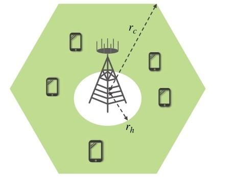
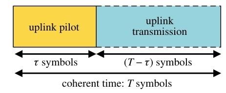
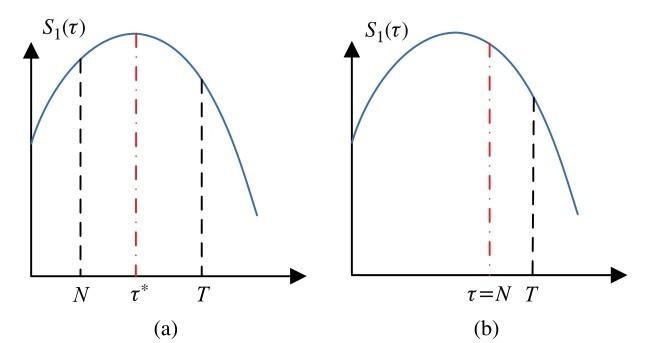
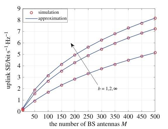
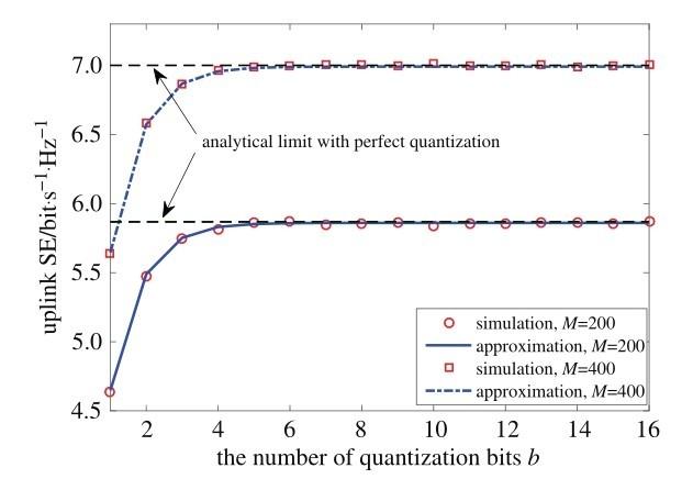
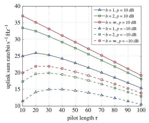

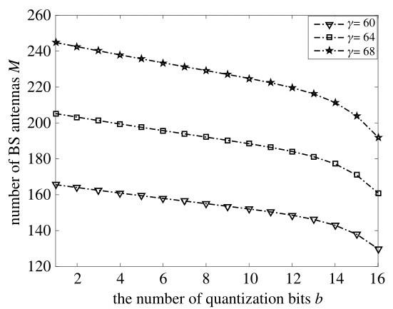
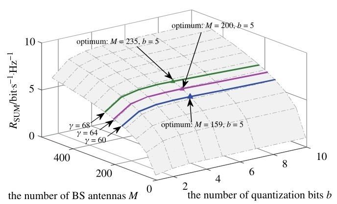
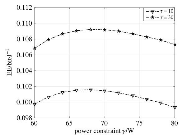
