the Engineering Research Centers Program of the National Science Foundation under NSF Cooperative Agreement. EEC-0812056
作者简介 About authors
Michael B. Rahaim is a postdoctoral researcher in the Department of Electrical and Computer Engineering at Boston University. His current research focuses on next generation wireless networks, software defined radio, and heterogeneous integration of wireless technologies including RF, OW, and VLC. Dr. Rahaim received his B. S. degree in electrical and computer engineering from RPI in 2007, and his M. S. degree and Ph. D. degree in computer engineering from Boston University in 2011 and 2015. He is a member of the IEEE and of the IEEE Communications Society.
E-mail:mrahaim@bu.edu.
Jessica Morrison researches the integration of micro-electromechanical systems (MEMS) with advanced solid-state lighting sources at Helux, a lighting technology company she founded in 2016. She completed her Ph. D. in physics at Boston University and graduated magna cum laude with a B. S. degree in physics from the University of Cincinnati. As a postdoctoral associate, her research is focused on visible light communications and testbed integration of MEMS micromirrors.
E-mail:morrisja@bu.edu.
Thomas D. C. Little is a profes-sor in the Department of Electrical and Computer Engineering at Boston Uni-versity. He is the associate director of the National Science Foundation Engi-neering Research Center for Lighting En-abled Systems and Applications(LESA), a collaboration of Rensselaer Polytech-nic Institute, the University of New Mexico, and Boston University. His current research focuses on pervasive com-puting using wireless technologies including applications in smart indoor environments, connected healthcare, and ve-hicular networking. Dr. Little received his B. S. degree in biomedical engineering from RPI in 1983, and his M. S. degree in electrical engineering and Ph. D. degree in com-puter engineering from Syracuse University in 1989 and 1991. He is a senior member of the IEEE, a member of the IEEE Computer and Communications Societies and a mem-ber of the Association for Computing Machinery.
E-mail:tdcl@bu.edu.
Abstract
Practical VLC (Visible Light Communication) systems are expected to leverage the lighting infrastructure in order to deliver data to devices in a lighting field. These devices can be static or quasistatic (e. g. , laptops or IoT devices); however, it is becoming clear that the preponderance of wireless data consumption is dominated by handheld mobile devices which will exhibit varying physical orientations and 3D dynamics. Because free-space optical and visible light communications are primarily line of sight, transmitter radiation patterns and receiver field of view are very important for predicting the data performance. Given dynamic emission characteristics, there is an opportunity to adapt to the receiver. The caveat of dynamic VLC systems is that the quality and distribution of the resulting illumination must be considered as part of the dual goal of providing high quality lighting. In this paper we investigate the impact of device orientation and mobility on static and then dynamic lighting emission under a multi-cell lighting model. From a source standpoint we consider the performance of beam control through angular control and beam focus for one or more sources in a lighting array. Analysis and simulation demonstrate that dynamic beam and luminaire control can increase the AP coverage range by 12. 8X under a 1. 67 m ceiling height. Furthermore, the use of multiple sources tracking device orientation and position can mitigate off-angle performance degradation by increasing redundancy in the number of available connections. Our proposed techniques, when applied in concert, successfully mitigate common concerns about the viability of VLC and indoor FSO (Free Space Optical Communication) methods related to signal occlusion and device dynamics.
Michael B. Rahaim. Beam control for indoor FSO and dynamic dual-use VLC lighting systems. [J], 2017, 2(4): 11-27 doi:10.1007/s41650-017-0041-7
1 Introduction
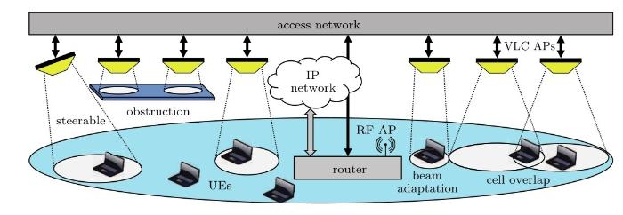
VLC is envisioned to tap the visible spectrum and enable the use of currently unused communication capacity for providing ubiquitous wireless access. Most overhead lighting is passive, LED or otherwise; but future lighting systems will be computer controlled and modulated for intensity, time of day, and the presence of occupants. Lighting systems enabled with VLC technology will additionally offer support for positioning and wireless data delivery. Because lighting and lighting systems require significant energy, the modulation of light is interpreted as opportunistic in that one would not normally use lighting as a communication medium due to its energy intensity. For this reason, VLC for data access is primarily a downlink technology (although there are other use cases envisioned, e. g. , underwater point-to-point communications, which can be characterized differently). A typical downlink scenario is illustrated in Fig.1, in which VLC cells incorporate beam steering and beam adaptation capabilities in order to improve coverage while increasing both reliability and capacity.
Figure 1
Downlink VLC network in a heterogeneous environment under the coverage of an RF small cell
In multi-cell/multi-user environments, AP (Access Point) deployment and UE (User Entity) distribution will impact the network’s aggregate performance. If UEs are at fixed locations, the lighting sources, or APs, can be strategically positioned; however, when UEs are mobile, as in the case of devices such as smart-phones, the system design must reconcile the need for both high data rates and broad spatial coverage. OWC (Optical Wireless Communications) can be designed for direct, LOS (Line of Sight) links, or for diffuse links. Given the directionality of the optical medium, LOS links have significantly higher SNR supporting higher data rates; however, the optical medium is also susceptible to blocking. In dynamic environments, the LOS path between an AP and UE may be obstructed; leading to a drastic degradation in the performance of the VLC link. Diffuse links have better room coverage characteristics; but operate at much lower data rates due to the reduction in signal power. RF small cells also offer wider coverage area; however, they do not benefit from the spatial reuse and aggregate capacity gains of densely distributed VLC networks.
When multiple light sources (luminaires) are involved, there is an opportunity to incorporate redundancy in the deployment of VLC APs in order to provide full coverage and increase network reliability (i. e. , mitigate the effect of occlusions). The challenge here is that overlapping regions must avoid the detrimental effects of interference in multi-user scenarios. Intelligent network management can utilize knowledge of relative UEs and APs in order to appropriately allocate resources and implement link handover methods. Each luminaire’s intensity can also be varied through“cell zooming”analogous to TPC(Transmission Power Control)in RF systems[1]. VLC cell zooming adaptively modifies the modulation depth of VLC signals in order to facilitate dynamic variations in the VLC coverage regions without altering the illumination profile.
In a dynamic lighting environment, it is possible to control shape and direction of the luminaires using MEMS mirrors[2]. Here, shape is typically modeled by Lambertian order or beam FWHM (Full Width Half Maximum) and direction is modeled as deviation angle from the normal. Thus, the key control dimensions are: (1) intensity, (2) beam width, and (3)direction. With these degrees of control, it is possible to engage an array of luminaires to track and adapt to the movement and orientation of a mobile device while maintaining suitable lighting for human consumption.
In general, we consider VLC as the broad category of OWC technologies that utilize the visible spectrum. VLC lighting systems encompass any VLC networks with the dual mission of providing illumination. Dynamic VLC systems encompass any VLC networks where the emission and/or acceptance pat terns can be modified in real time. Indoor FSO specifies the category of indoor OWC technologies that utilize highly direction pencil-beam transmitters. Accordingly, indoor FSO systems require precise alignment such that the emitted signal is focused in the direction of the receiver.
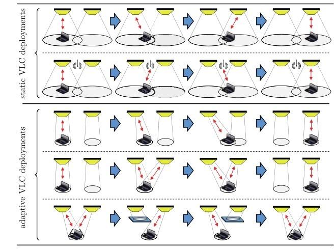
Fig.2depicts various VLC network techniques to accommodate mobility as a UE transits between VLC cells. With a static VLC deployment, the connection is either transferred directly to the neighboring VLC cell through HHO(Horizontal Handover)in the overlap region or through a pair of VHOs(Vertical Handovers)such that the RF connection is used in the interference region. In the adaptive scenarios, dynamic VLC transmission is used whereby the VLC signal follows the motion path of the UE.
Figure 2
VLC network coverage scenarios showing (top to bottom): horizontal handover between VLC cells; vertical handover in an RF/VLC HetNet; beam steering for increased single cell coverage area; beam steering with aggregation for increased capacity; and beam steering with LOS blockage for increased reliability
Adaptation can improve coverage and reliability of the VLC network; but must also accommodate the lighting mission. This implies that the dynamic variations in the light field must maintain compatibility with the illumination requirements. Lighting control algorithms may adapt the collective set of VLC APs to provide the desired illumination while a subset of the APs are directed for communications with specific UEs. Alternatively, a subset of the optical power from any given luminaire can be redirected such that a UEs received signal strength is improved but the change in the illumination profile is relatively small.
In the first adaptive scenario, the UE remains connected to the first AP for a longer period due to the improved signal strength from the directed light. This increases the potential coverage area of a VLC AP and reduces the number of handovers required. In the second adaptive scenario, multiple APs are simultaneously directed at the UE—providing a smoother handover and increasing potential capacity through either aggregation or cooperative transmission. Finally, the third adaptive scenario shows how potential connection to multiple APs provides reliability in the case of an obstruction that blocks the LOS path between the UE and one of the available APs.
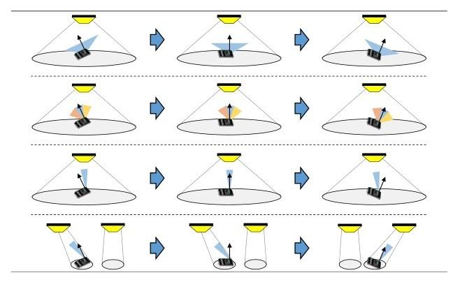
At the receiver, device orientation (how people hold the phone) also impacts the performance of a VLC connection. Fig.3illustrates this challenge with multiple receiver architectures. There are various ways to attack this challenge, for example, through receiver design(e. g. , image-based, SLMbased, insect eye, etc. ); however, in each scenario we can benefit from the APs directed transmission in order to achieve the best signal based on the device position and orientation.
Figure 3
Rotating UE scenarios showing (top to bottom): wide FOV receiver; multi-element receiver; steerable receiver; and steerable transmitter/receiver pair
In this paper we investigate the use of the lighting control dimensions (intensity, beam width, di rection)under different device positions and orientations in an array of luminaires in order to maximize achievable signal strength while improving both coverage and reliability through AP redundancy. The proposed solutions for adaptive transmitters and receivers successfully address common VLC network challenges related to light occlusion and dynamic environments.
Related work falls into categories of (a) beam steering using SLMs, (b)the impacts of receiver design, and (c) small-cell array-based VLC analysis. Prior work in VLC beam steering includes MEMS SLMs such as mirrors[2,3,4,5]and piezioelectric[6]de vices. Efforts in beam steering apply primarily to an indoor FSO model with narrow beams or matching receivers[7]; but includes use of static steering with gratings[8,9]or holographic techniques[10]. Coverage and lighting are considered in Ref. [11]; but with fixed-orientation sources and without experimental validation. Ref. [12]considers how spatial layout can improve coverage and SNR while considering lighting goals. Regarding receiver orientation, it is well known that mobile UEs such as smartphones have existing limitations on data rate when a phone camera is used. But with future enhancements, smartphones will adopt VLC receivers that must account for rotation and tilt with respect to VLC sources. Mobile device orientation has been studied generally[13]and for VLC in a number of works[14,15]. Lastly, there is much work on small cell VLC networks–including the incorporation of alternative media such as RF[7,16,17].
Our work is distinguished by dynamic steering and focus, the use of multiple beams to extend data coverage, and the incorporation of the lighting specification in the system design. We also provide experimental data supporting our simulations. The remainder of this paper is organized as follows. Section 2 introduces ultra-dense wireless networks, OWC, and directional VLC. Section 3 describes new models, predicted performance, and characterization of AP coverage with respect to a single VLC AP. Section 4 shows experimental results in the evaluation of a MEMS-based directional VLC transmitter. Sec tion 5 introduces hybrid approaches considering narrow beams in lighting and evaluates multi-coverage in networks with multiple VLC APs. Section 6 concludes the paper.
2 Background and assumptions
In this work, we explore the impact of dynamic OWC devices on network performance. We first provide background in relation to (1) ultra-dense wireless networks with multiple APs and UEs; (2)static OWC networks and requirements of dual-use VLC systems; and (3) dynamic VLC systems with adjustable emission profile. We also introduce assumptions related to the device capabilities along with models for the operating environment and the optical channel.
2. 1 Ultra-dense wireless networks
Next generation wireless networks will need to accommodate an increasing density of wireless devices along with increasing data demand per device. Given the high percentage of traffic occurring in indoor environments, strategically placed ultra-dense wireless networks have been proposed in order to provide additional wireless capacity where it is needed most. In addition to the growing data demand, wireless devices are becoming increasingly diverse (e. g. , IoT devices, wearables, mobiles, laptops/tablets, etc. ). This diversity implies that future wireless networks must also accommodate a broad range of operating conditions(e. g. , rate requirements, mobility, etc. ).
In the case of ultra-dense wireless networks, simply moving through a room or changing a UEs orientation implies multiple changes in the potential network connections. Accordingly, practical implementation must account for coverage and reliability in multi-cell/multi-user networks with mobile and quasi-static devices. Multi-tier HetNet (Heterogeneous Network)integration is one technique to provide the coverage of larger cells along with the aggregate capacity of ultra-dense wireless networks. Alternatively, redundancy in the AP deployment can allow a given UE to have multiple potential connections at any given location in the network. This multi-coverage can increase link capacity and improve reliability.
2. 2 Indoor OWC
OWC is considered to be an excellent candidate for ultra-dense wireless networks due to the directionality of the optical channel. Specifically, the growing adoption of LED-based lighting for indoor illumination has drawn considerable interest in dual-use VLC for illumination and data transfer. The placement of luminaires for indoor illumination can be opportunistically utilized for dense deployment of VLC APs since lighting needs and data demand are highly synergistic. In addition, network connected smart lighting provides an available infrastructure and access network for VLC transmitters.
OWC is typically implemented via IM/DD (Intensity Modulation with Direct Detection). For a point source transmitter and receiver, the LOS optical channel DC gain is defined as[18]
where and represent the transmitted and received optical power from the ith transmitter at the jth receiver. The visibility of the ith transmitter at the jth receiver is defined as . It is set to 1 if a LOS path exists and to 0 otherwise. The functions GT(·) and GR(·) represent the emission profile of the transmitter and the gain function of the receiver, respectively. The distance between the ith transmitter and the jth receiver is denoted by and the angles and represent the angles of emission and acceptance, respectively.
For the transmitter gain model, GT(·), we consider a Lambertian source:
where is the Lambertian order and relates to the semiangle at half power. We assume a base case of a pure Lambertian source with m=1 which relates to a 60◦ half angle. The receiver’s gain function is modeled as
where A is the photosensor area, is the filter transmittance, and is the gain from any additional optics.
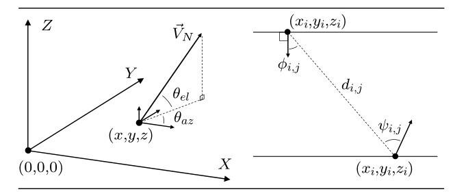
The absolute and relative coordinates of the observed environmental model are depicted in Fig.4. We model the transmitter and receiver as point sources with transmitter locations denoted by and receiver locations denoted by . The orientation of a transmitter or receiver is shown by its normal vector , and is defined in terms of azimuth and elevation angles . The vector represents a pointing vector from transmitter i towards receiver j and represents a pointing vector from receiver j towards transmitter i. Emission and acceptance angles are relative to the specified AP/UE pair (shown in a 2 dimensional representation in Fig.4). In a 3D model, is the angle between and . Similarly, is the angle between and .
Figure 4
Source and sensor model showing absolute (left) and relative (right) coordinate systems
The optical channel’s angle dependence and susceptibility to blocking imply that coverage in a multicell/multi-user VLC network is viewed in a different way than the conventional cellular model which is based on distance from the AP. As an example, a UE located directly below an AP may find that an alternative AP is preferable due to the receiver’s orientation and/or blockage in the LOS path to the first AP. OWC networks implementing dual-use VLC are also constrained by the illumination requirements of the lighting system. Conventional lighting deployments often require overlapping emission from neighboring luminaires. This overlap adds a degree of redundancy to the network, increasing the number of available connections in the overlap regions. Overlapping coverage also adds interference when multiple APs attempt to transmit simultaneously – degrading the performance of the network. Heterogeneous RF/VLC networks have been proposed where RF provides coverage and reliability while static VLC cells add supplemental capacity[16,17,19]. In this case, the luminaires are often provisioned to satisfy the lighting mission and then used opportunistically to add capacity via VLC. Dynamic OWC networks can adapt their coverage to the distribution of UEs in real time; but dual-use VLC networks must continue to satisfy the lighting mission.
2. 3 Steerable/directional OWC
One implication of fully directional VLC is a reduction in the uniformity of the light field. The network requirements on signal strength may contradict standards constraining the maximum and average luminous flux[20]. However, this can be mitigated using multiple adaptive sources by reallocating resources based on user device orientation or mobility. As the number of dynamic APs increases, the potential for maintaining optimized signal strength while operating within the lighting constraints also increases. Furthermore, the proportion of modulated light can be tuned, steering only the VLC component. Similarly, indoor mobility can be realized by allocating a portion of the light field for VLC. Both acquisition and tracking have been implemented using a closedloop MEMS steering system[21]. The methods used for tracking are compatible in both narrow FSO and in broad emission VLC.
3 Access point coverage
With a validation of the potential for the steerable VLC sources, we now consider the impact of these devices on increasing the coverage area of a single AP for a specified performance threshold. We evaluate and analyze the tradeoffs between instantaneous coverage and potential coverage as the signal source becomes more directional.
3. 1 Access point coverage analysis
Directional communications can increase the transmission range of a VLC AP by focusing the transmitted optical power in the direction of a UE. When perfectly aligned, the received signal strength is maximized; although, practical systems must account for imperfect alignment. Consider a receiver with a LOS path and without optics(i. e. , no filter or optical gain). In this case, . For comparison, we observe the following scenarios where the achievable received optical power is determined from equations 1, 2 and 3 when the AP is within the receiver’s FOV(Field of View)and 0 otherwise.
1. Broad Emission (Normal): Static transmitter directed downward with m=1.
2. Directional(Fixed): Static transmitter directed downward with .
3. Rotated Rx: Rx rotation towards AP().
4. Rotated Tx: Tx rotation towards UE().
5. Rotated Tx and Rx: Tx and Rx rotated towards each other(, ).
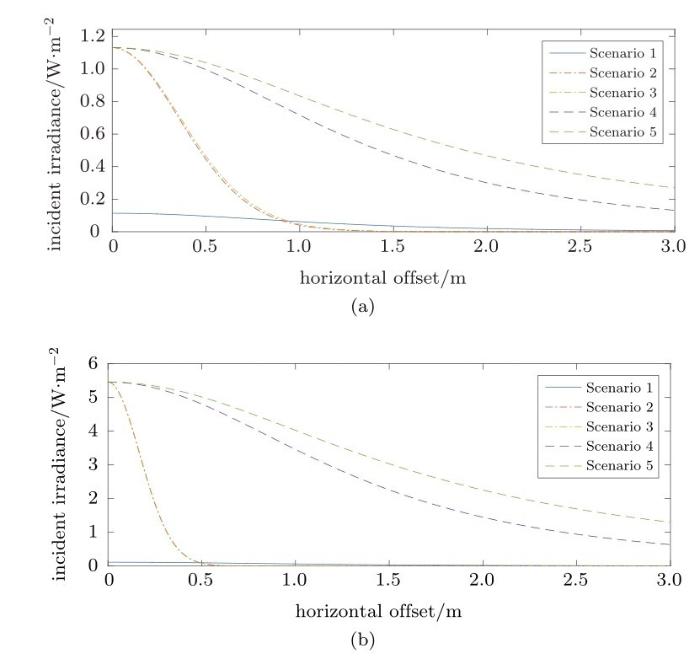
Fig.5depicts the received optical power for each of the above scenarios as the UE is moved horizontally off axis from the AP. Without loss of generality, the results indicate a unit transmit power and unit area (i. e. , irradiance[W/m2]at the receiver surface when Pt=1 W). The vertical distance between the AP and UE is 1. 67 m. For comparison, we show results for and . In Scenarios 1, 2, and 4, the receiver is directed upwards and normal to the user plane.
Figure 5
Signal strength vs.horizontal offset.(a) φ1/2=15.4°; (b) φ1/2=6. 9°
For each directional scenario, the signal strength directly below the AP shows improvement over the broad emission scenario. As the degree of directionality (i. e. , m) increases, the range of improved coverage for Scenarios 2 and 3 decreases. Note that the directional receiver shows minimal improvement over the fixed directional scenario due to the cosine function of the emission angle being raised to the mth power. When steerable directional transmission is used (i. e. , Scenarios 4 and 5), the maximal signal power for a given m is directed towards the UE. In this case, the rotation of the receiver has a larger relative impact on the received signal power.
The directional transmitter scenarios show excellent improvement over the broad emission scenario when the transmitter is aligned with the UE. However, there is a tradeoff in that the transmitter’s orientation must be dynamically changed and the coverage at any given instant is dependent on the current orientation. Accordingly, Fig.5shows the potential received optical power assuming perfect alignment at every position. We define an AP’s instantaneous coverage and potential coverage to account for these differences.
3. 2 Potential coverage
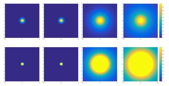
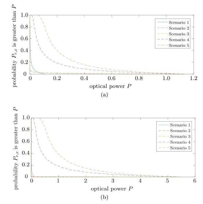
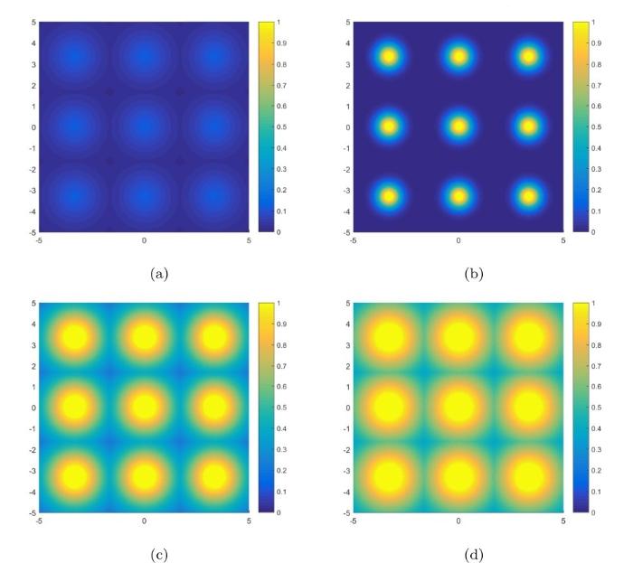
We first explore the potential coverage of a single AP. Fig.6shows a 2 dimensional representation of the incident irradiance over a 5 m × 5 m surface for Scenarios 2~5 when and . For comparison, we maintain a color axis range of 0~1 W(bright yellow indicates that the irradiance is greater than 1 W/m2). Fig.7depicts these results in the form of a complementary cumulative distribution function.
Fig.6shows that the area with irradiance greater than 1 W/m2is larger than 1 m2. This would seem contradictory to the total transmitted optical power of 1 W. The reasoning is that potential coverage relates maximum received signal power over all potential orientations. Given the increase in signal strength relative to Scenario 1, it is clear that a percentage of the transmit power can be used in the directional transmission scenarios while still providing a coverage improvement. This is beneficial for dualuse VLC systems since the portion of directed optical power can be relatively small in order to provide minimal perturbations in the illumination profile.
Figure 6
Signal strength (incident irradiance) depicting potential coverage for Scenarios 2 through 5 (left to right) at 1.67 m vertical distance from transmitter with half angle 15.4° (top) and 6. 9° (bottom)
Figure 7
ccdf (Complementary cdf) of the achievable signal strength.(a) complementary cdf of maximum Rx signal W (φ1/2=15.4°); (b) complementary cdf of maximum Rx signal W(φ1/2=6. 9°)
Figure 8
Signal strength depicting instantaneous coverage.(a) a static VLC AP with m=1; (b) a steerable VLC AP with half angle of 15.4°; (c) a steerable VLC AP with half angle of 6. 9°
3. 3 Instantaneous coverage
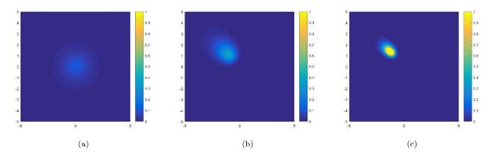
We define instantaneous coverage in relation to the incident irradiance for a given receiver orientation when the transmitter orientation is specified. In the case of static transmission scenarios, the instantaneous coverage does not change(i. e. , it is equivalent to the potential coverage). Fig.8shows the coverage for Scenario 1 and the instantaneous coverage for a directed transmitter with half angle 15. 4◦and 6. 9◦. Steerable results show instantaneous coverage when the transmitter is rotated with and .
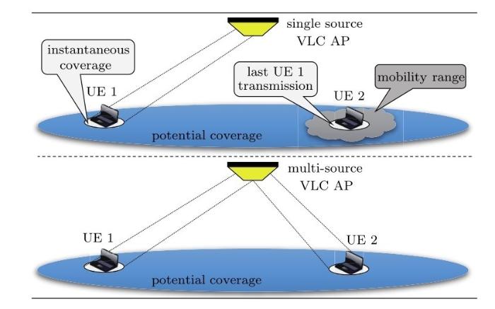
The tradeoff between potential coverage and instantaneous coverage becomes more relevant in multi-user environments. Highly directional steerable VLC transmitters provide a broad potential coverage region while limiting interference. However, when the instantaneous coverage area is small, an AP cannot maintain simultaneous connection with multiple UEs with a single source. Broad emission transmitters can utilize time, frequency, and/or code division multiple access schemes; however, a highly directional source must allocate time in which it is directed at different UEs. This multiple access challenge can be addressed with multiple directional sources per AP; but this implies additional hardware and must accommodate the worst case scenario for the number of UEs per cell. These techniques are depicted in Fig.9for a scenario with 2 UEs.
When a single directional source is time multiplexed to accommodate multiple UEs, the aggregate capacity is reduced due to the necessary time for transferring between UEs (i. e. , redirecting the optical signal). As an example, the throughput in the case of 2 UEs is
where ttrans[s]is the time to transfer between links, Ci[b/s]is the capacity of the link for the ith UE, and th, i[s]is the time that the link holds on the ith UE between transfers.
For shorter holding periods, throughput is lower due to the higher percentage of time spent transferring between connections. Longer holding periods improve system throughput; however, this also implies a longer time between active connections for a given UE. If there are N UEs covered by a single transmitter and a round-robin service discipline is used, the time between simultaneous connections for the ith UE is
Figure 9
Multi-user scenario for directional VLC APs with single source (top) and multiple sources (bottom)
For a mobile UE, there is a range of motion (translational and rotational) that can occur between simultaneous connections. In order to avoid the need to reacquire a connection, the system must either (a) implement tracking with an external technique that maintains the UEs status while the source is servicing other UEs, (b) assure that the time between connections is less than the time that it would take for the UE to move out of range of the transmitter’s instantaneous coverage from its last connection with the UE, or(c)implement predictive techniques in order to estimate UE movement during the period of time when it is not connected. Note from Eq. 10 that increasing the number of UEs connected to a single transmitter would require a reduction in the average holding time in order to maintain a fixed maximum tout, i.
4 Experimental validation
The experimental design is described in the first portion of this section as it relates to the variables defined in section 2. Results are shown for a 2D model of the coverage area. These results can be generalized to the 3D case that includes the device; but this is not shown here.
4. 1 Components
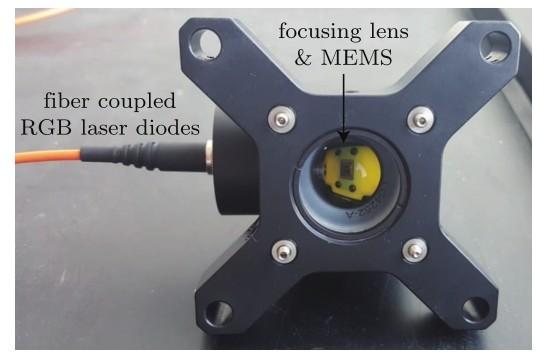
Three visible light LDs (Laser Diodes) at 450 nm, 520 nm, and 630 nm are coupled using dichroic beam splitters and focused into a 400 µm fiber with 0.5 NA. Fig.10shows the transmitter element where the fiber and MEMS are visible. The output of the fiber is focused onto a MEMS micromirror which is packaged with an anti-reflective cover. The reflected beam is then incident on a secondary concave lens to enhance the angle of reflection, followed by a holographic diffuser element.
Figure 10
Image of transmission element without the diffuser at the output in order to image the interior
The maximum optical power output of each LD is 20 mW; however, the actual output is dependent on the modulation depth of the red LD. To produce white light, the red LD is set with a fixed DC offset current and a modulation is added. The green and blue LDs are then introduced using two DC offsets until the transmitted light is visibly white. In a future setup, the green and blue LDs can be modulated either with the red LD or in a wavelength division multiplexing scheme.
Figure 11
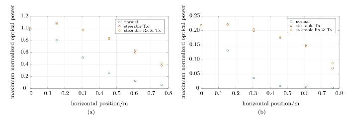
Signal strength vs.horizontal offset for Φ1/2=6. 9° with several Rx offset positions (colors)
The MEMS devices are controllable using a commercially available microcontroller and can respond at microsecond time scales[22]. The optical angular range of this particular device is approximately ±12◦and is expanded to nearly ±30◦, until the limitation is the exit pupil of the system. At the exit pupil, two exchangeable diffusers are utilized to provide two illumination scenarios whereby or . The Rx element is a Thorlabs avalanche photodiode(APD120A2)continuously positioned at for every measurement. However, the relative horizontal offset of the Rx and Tx positions vary depending on the measurement type.
4. 2 Alignment
A sweep of the micromirror voltage is performed along in order to calibrate the voltage required to tilt the mirror to a specified angle. The optical power is initially plotted against applied voltage and fitted to a Gaussian. The voltage at the peak of the optical power fit is then known to correspond to the angle along Vi, j. Information about the voltage to micromirror direction is then used to perform all subsequent measurements.
Fig.11illustrates results of the alignment procedure and the impact of Tx/Rx alignment on signal strength. Each color represents an Rx offset position and each data point is the signal strength when the Tx is pointed at the offset position on the x-axis. The transmitted signal direction is swept and the point of maximum signal strength for each Rx position is obtained. All measurements are normalized to the maximum optical power when .
In this case, the transmitted signal is modulated at 40 Mb/s and the DC amplitude is removed in order to remove ambient light effects such as sunlight variation within the lab space. This type of measurement introduces a power discrepancy when the horizontal offset is zero. The increase in optical power is due to reflected light which is not reflected from the movable mirror. A small portion of the reflected light is from the backplane and the MEMS packaging. Thus, when the mirror is steered, approximately 10% of the optical power remains at .
4. 3 Signal strength measurements
While the alignment procedure is informative for the overall impact of Rx/Tx alignment on signal strength, the results do not include the effects of Rx direction. Since the difference in signal strength when the Rx is normal to when it is directed along Vj, iis expected to be much smaller than the signal difference for a static Tx to that of a rotated Tx, a secondary set of data is compiled. In the second set, the LD is no longer modulated as it is unnecessary to obtain the information on power differences. The Rx is positioned at some offset and the power is measured for a directional setup with a static transmitter and receiver system. The mirror is then scanned through the same angles as in the previous section to obtain the maximum optical power when the Tx is rotated toward the UE. Prior to moving the Rx, the Rx is rotated toward the AP and the micromirror is scanned again, providing the maximum optical power obtainable with a rotated Tx and Rx system.
Figure 12
Signal strength vs.horizontal offset.(a) Φ1/2=6.9°; (b) Φ1/2=15. 4°
Fig.12shows the maximum optical power received with a fixed Rx/Tx system, a rotated Tx system, and a rotated Tx and Rx system. The values are normalized to the maximum optical power at zero horizontal offset. However, since these measurements are based on a DC signal to start, the non-steerable 10% of the optical power is now subtracted rather than added to the first measurement. This validates the first theory that the first measurement is an outlier. Fig.12 also illustrates the same pattern for a more diffuse illumination. Although, the first outlier is not significant as the beam angle is more diffuse to begin with.
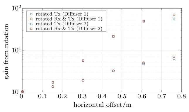
As was hypothesized in section 3, rotating the Rx has an impact on the system but the enhancement in signal strength using a rotated Tx is the dominant source of gain when compared to rotating both the Rx and Tx toward each other. The relative gains are shown in Fig.13which show that, as the divergence angle increases, the relative improvement in signal quality from directional to rotated becomes larger.
Figure 13
Gains for Scenarios 4 and 5 for Φ1/2=6.9° (Diffuser 1) and Φ1/2=15. 4° (Diffuser 2)
5 Network coverage
In this section, we analyze the coverage potential from a grid of directional VLC transmitters. We explore the potential signal strength improvement as well as the reliability improvement in terms of the number of available connections at various points in the environment.
5. 1 Network coverage
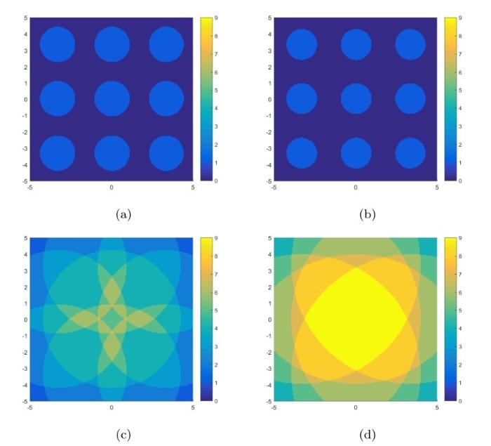
Similar to the single AP results from section 3, Fig.14depicts a 5 m × 5 m surface with the potential coverage from a grid of 9 directional transmitters. Fig.15shows the corresponding ccdf of the potential coverage within the environment for transmitter half angle 15. 4◦and 6. 9◦.
Figure 14
Signal strength depicting potential coverage for a 3 × 3 grid of transmitters with half angle of 15.4°. (a)normal; (b) directional W; (c) rotated Tx W; (d) rotated Tx &Rx W
Figure 16
Number of APs capable of achieving 5% signal strength threshold with half angle of 15.4°. (a) Scenario 1; (b) Scenario 2; (c) Scenario 4; (d) Scenario 5
The results of the multi-cell network show that increasing the directionality of fixed orientation transmitters will improve peak performance while decreasing the coverage at lower power thresholds. As an example, the maximum incident irradiance goes from 0.11 W/m2to 1. 13 W/m2when increasing the directionality from to . However, 50% of the room is able to achieve 0.042 W/m2in the former case whereas 50% of the room is less than 0.007 W/m2in the later case. The fixed directional transmitters with only achieve 0.042 W/m2over 30% of the room. When dynamic transmitters are utilized, the peak remains the same as in the case of the fixed directional transmitters (occurring directly below the transmitters); however, 50% of the environment can achieve an incident irradiance of 0.54 W/m2for an upwards facing receiver and 0.69 W/m2when the receiver is oriented towards the AP with the strongest signal.
5. 2 Multi-coverage
We are interested in the redundancy of potential connections in order to evaluate the reliability in environments where the LOS path could be obstructed. Expanding on the results from section 5. 1, Fig.16highlights the number of APs that can provide an incident irradiance greater than 5% of the maximum achievable irradiance from the directional transmitter(i. e. , 0.056 5 W/m2for and 0.273 W/m2for ). Results for the same threshold are also presented for Scenario 1. The attainable coverage area for a single AP in terms of signal strength is larger for Scenario 1 than for Scenario 2; however, performance may ultimately be worse when multiple transmitters are simultaneously active since the broader emission also implies that interference from neighboring APs is higher in Scenario 1.
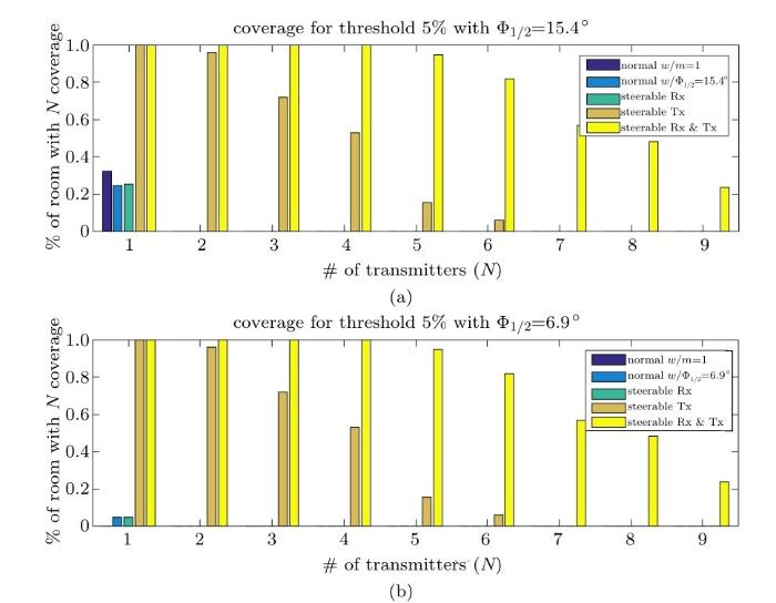
Fig.16also shows that the number of viable APs increases when the transmitter is dynamic. In the case of the dynamic transmitter and receiver, all 9 of the APs can connect to approximately 22% of the room. The percentage of the room with N viable APs(i. e. , N-Coverage)is shown with more detail in Fig.17for transmitters with half angle 15. 4◦and 6. 9◦.
Figure 17
Percentage of room that is capable of achieving N-coverage at a 5% signal strength threshold.(a)φ1/2=15.4°; (b) φ1/2=6. 9°
6 Conclusion and future work
The use of light steering, focus, and intensity control has the potential to optimize the number of required access points needed to realize data and lighting coverage. In this paper we study the performance gain provided by the use of VLC luminaires with dynamic control of the emission pattern. We show tradeoffs between static and dynamic VLC transmission. We provide empirical characterization of the coverage from a controllable MEMS setup, simulate the instantaneous and potential coverage of single VLC AP, and evaluate the network reliability gain in regard to multi-coverage.
The results indicate that a single AP can increase its coverage area by more than 15X at 10% of the peak power when moving from a broad emis sion transmitter to a dynamic directional transmitter. This allows mobile UEs to maintain a connection longer and reduces the number of required handovers. It also offers potential to direct a small percentage of the transmitted optical power and still maintain similar performance. In addition, we show the modeled network of 9 transmitters can increase the coverage area for 50% of the peak power by approximately 12. 8X with a peak power gain of 10X. These performance metrics are further improved with increased transmission directionality. Finally, the network results indicate an excellent improvement in network reliability with the potential to connect to multiple APs throughout the modeled environment; providing redundancy in the connectivity and allowing the network to mitigate performance degradation caused by dynamic obstructions.
The authors have declared that no competing interests exist.
SINR analysis and cell zooming with constant illumination for indoor VLC networks
1
2013
... When multiple light sources (luminaires) are involved, there is an opportunity to incorporate redundancy in the deployment of VLC APs in order to provide full coverage and increase network reliability (i. e. , mitigate the effect of occlusions). The challenge here is that overlapping regions must avoid the detrimental effects of interference in multi-user scenarios. Intelligent network management can utilize knowledge of relative UEs and APs in order to appropriately allocate resources and implement link handover methods. Each luminaire’s intensity can also be varied through“cell zooming”analogous to TPC(Transmission Power Control)in RF systems[1]. VLC cell zooming adaptively modifies the modulation depth of VLC signals in order to facilitate dynamic variations in the VLC coverage regions without altering the illumination profile. ...
Directional visible light communication signal enhancement using a varifocal micromirror with four degrees of freedom
2
2016
... In a dynamic lighting environment, it is possible to control shape and direction of the luminaires using MEMS mirrors[2]. Here, shape is typically modeled by Lambertian order or beam FWHM (Full Width Half Maximum) and direction is modeled as deviation angle from the normal. Thus, the key control dimensions are: (1) intensity, (2) beam width, and (3)direction. With these degrees of control, it is possible to engage an array of luminaires to track and adapt to the movement and orientation of a mobile device while maintaining suitable lighting for human consumption. ...
... Related work falls into categories of (a) beam steering using SLMs, (b)the impacts of receiver design, and (c) small-cell array-based VLC analysis. Prior work in VLC beam steering includes MEMS SLMs such as mirrors[2,3,4,5]and piezioelectric[6]de vices. Efforts in beam steering apply primarily to an indoor FSO model with narrow beams or matching receivers[7]; but includes use of static steering with gratings[8,9]or holographic techniques[10]. Coverage and lighting are considered in Ref. [11]; but with fixed-orientation sources and without experimental validation. Ref. [12]considers how spatial layout can improve coverage and SNR while considering lighting goals. Regarding receiver orientation, it is well known that mobile UEs such as smartphones have existing limitations on data rate when a phone camera is used. But with future enhancements, smartphones will adopt VLC receivers that must account for rotation and tilt with respect to VLC sources. Mobile device orientation has been studied generally[13]and for VLC in a number of works[14,15]. Lastly, there is much work on small cell VLC networks–including the incorporation of alternative media such as RF[7,16,17]. ...
TipTilt-Piston micromirror with integrated large range variable focus for smart lighting systems
1
2015
... Related work falls into categories of (a) beam steering using SLMs, (b)the impacts of receiver design, and (c) small-cell array-based VLC analysis. Prior work in VLC beam steering includes MEMS SLMs such as mirrors[2,3,4,5]and piezioelectric[6]de vices. Efforts in beam steering apply primarily to an indoor FSO model with narrow beams or matching receivers[7]; but includes use of static steering with gratings[8,9]or holographic techniques[10]. Coverage and lighting are considered in Ref. [11]; but with fixed-orientation sources and without experimental validation. Ref. [12]considers how spatial layout can improve coverage and SNR while considering lighting goals. Regarding receiver orientation, it is well known that mobile UEs such as smartphones have existing limitations on data rate when a phone camera is used. But with future enhancements, smartphones will adopt VLC receivers that must account for rotation and tilt with respect to VLC sources. Mobile device orientation has been studied generally[13]and for VLC in a number of works[14,15]. Lastly, there is much work on small cell VLC networks–including the incorporation of alternative media such as RF[7,16,17]. ...
Electrothermally actuated tip-tilt-piston micromirror with integrated varifocal capability
1
2015
... Related work falls into categories of (a) beam steering using SLMs, (b)the impacts of receiver design, and (c) small-cell array-based VLC analysis. Prior work in VLC beam steering includes MEMS SLMs such as mirrors[2,3,4,5]and piezioelectric[6]de vices. Efforts in beam steering apply primarily to an indoor FSO model with narrow beams or matching receivers[7]; but includes use of static steering with gratings[8,9]or holographic techniques[10]. Coverage and lighting are considered in Ref. [11]; but with fixed-orientation sources and without experimental validation. Ref. [12]considers how spatial layout can improve coverage and SNR while considering lighting goals. Regarding receiver orientation, it is well known that mobile UEs such as smartphones have existing limitations on data rate when a phone camera is used. But with future enhancements, smartphones will adopt VLC receivers that must account for rotation and tilt with respect to VLC sources. Mobile device orientation has been studied generally[13]and for VLC in a number of works[14,15]. Lastly, there is much work on small cell VLC networks–including the incorporation of alternative media such as RF[7,16,17]. ...
Multiplexed broadband beam steering system utilizing high speed MEMS mirrors
1
2009
... Related work falls into categories of (a) beam steering using SLMs, (b)the impacts of receiver design, and (c) small-cell array-based VLC analysis. Prior work in VLC beam steering includes MEMS SLMs such as mirrors[2,3,4,5]and piezioelectric[6]de vices. Efforts in beam steering apply primarily to an indoor FSO model with narrow beams or matching receivers[7]; but includes use of static steering with gratings[8,9]or holographic techniques[10]. Coverage and lighting are considered in Ref. [11]; but with fixed-orientation sources and without experimental validation. Ref. [12]considers how spatial layout can improve coverage and SNR while considering lighting goals. Regarding receiver orientation, it is well known that mobile UEs such as smartphones have existing limitations on data rate when a phone camera is used. But with future enhancements, smartphones will adopt VLC receivers that must account for rotation and tilt with respect to VLC sources. Mobile device orientation has been studied generally[13]and for VLC in a number of works[14,15]. Lastly, there is much work on small cell VLC networks–including the incorporation of alternative media such as RF[7,16,17]. ...
Diversity combining and piezoelectric beam steering for multi-element VLC networks
1
2016
... Related work falls into categories of (a) beam steering using SLMs, (b)the impacts of receiver design, and (c) small-cell array-based VLC analysis. Prior work in VLC beam steering includes MEMS SLMs such as mirrors[2,3,4,5]and piezioelectric[6]de vices. Efforts in beam steering apply primarily to an indoor FSO model with narrow beams or matching receivers[7]; but includes use of static steering with gratings[8,9]or holographic techniques[10]. Coverage and lighting are considered in Ref. [11]; but with fixed-orientation sources and without experimental validation. Ref. [12]considers how spatial layout can improve coverage and SNR while considering lighting goals. Regarding receiver orientation, it is well known that mobile UEs such as smartphones have existing limitations on data rate when a phone camera is used. But with future enhancements, smartphones will adopt VLC receivers that must account for rotation and tilt with respect to VLC sources. Mobile device orientation has been studied generally[13]and for VLC in a number of works[14,15]. Lastly, there is much work on small cell VLC networks–including the incorporation of alternative media such as RF[7,16,17]. ...
Design and demonstration of a 400 Gb/s indoor optical wireless communications link
2
2016
... Related work falls into categories of (a) beam steering using SLMs, (b)the impacts of receiver design, and (c) small-cell array-based VLC analysis. Prior work in VLC beam steering includes MEMS SLMs such as mirrors[2,3,4,5]and piezioelectric[6]de vices. Efforts in beam steering apply primarily to an indoor FSO model with narrow beams or matching receivers[7]; but includes use of static steering with gratings[8,9]or holographic techniques[10]. Coverage and lighting are considered in Ref. [11]; but with fixed-orientation sources and without experimental validation. Ref. [12]considers how spatial layout can improve coverage and SNR while considering lighting goals. Regarding receiver orientation, it is well known that mobile UEs such as smartphones have existing limitations on data rate when a phone camera is used. But with future enhancements, smartphones will adopt VLC receivers that must account for rotation and tilt with respect to VLC sources. Mobile device orientation has been studied generally[13]and for VLC in a number of works[14,15]. Lastly, there is much work on small cell VLC networks–including the incorporation of alternative media such as RF[7,16,17]. ...
... [7,16,17]. ...
Steerable pencil beams for multi-Gbps indoor optical wireless communication
1
2014
... Related work falls into categories of (a) beam steering using SLMs, (b)the impacts of receiver design, and (c) small-cell array-based VLC analysis. Prior work in VLC beam steering includes MEMS SLMs such as mirrors[2,3,4,5]and piezioelectric[6]de vices. Efforts in beam steering apply primarily to an indoor FSO model with narrow beams or matching receivers[7]; but includes use of static steering with gratings[8,9]or holographic techniques[10]. Coverage and lighting are considered in Ref. [11]; but with fixed-orientation sources and without experimental validation. Ref. [12]considers how spatial layout can improve coverage and SNR while considering lighting goals. Regarding receiver orientation, it is well known that mobile UEs such as smartphones have existing limitations on data rate when a phone camera is used. But with future enhancements, smartphones will adopt VLC receivers that must account for rotation and tilt with respect to VLC sources. Mobile device orientation has been studied generally[13]and for VLC in a number of works[14,15]. Lastly, there is much work on small cell VLC networks–including the incorporation of alternative media such as RF[7,16,17]. ...
Free-space transmission with passive 2D beam steering for multigigabit-per-second per-beam indoor optical wireless networks
1
2016
... Related work falls into categories of (a) beam steering using SLMs, (b)the impacts of receiver design, and (c) small-cell array-based VLC analysis. Prior work in VLC beam steering includes MEMS SLMs such as mirrors[2,3,4,5]and piezioelectric[6]de vices. Efforts in beam steering apply primarily to an indoor FSO model with narrow beams or matching receivers[7]; but includes use of static steering with gratings[8,9]or holographic techniques[10]. Coverage and lighting are considered in Ref. [11]; but with fixed-orientation sources and without experimental validation. Ref. [12]considers how spatial layout can improve coverage and SNR while considering lighting goals. Regarding receiver orientation, it is well known that mobile UEs such as smartphones have existing limitations on data rate when a phone camera is used. But with future enhancements, smartphones will adopt VLC receivers that must account for rotation and tilt with respect to VLC sources. Mobile device orientation has been studied generally[13]and for VLC in a number of works[14,15]. Lastly, there is much work on small cell VLC networks–including the incorporation of alternative media such as RF[7,16,17]. ...
20 Gb/s mobile indoor visible light communication system employing beam steering and computer generated holograms
1
2015
... Related work falls into categories of (a) beam steering using SLMs, (b)the impacts of receiver design, and (c) small-cell array-based VLC analysis. Prior work in VLC beam steering includes MEMS SLMs such as mirrors[2,3,4,5]and piezioelectric[6]de vices. Efforts in beam steering apply primarily to an indoor FSO model with narrow beams or matching receivers[7]; but includes use of static steering with gratings[8,9]or holographic techniques[10]. Coverage and lighting are considered in Ref. [11]; but with fixed-orientation sources and without experimental validation. Ref. [12]considers how spatial layout can improve coverage and SNR while considering lighting goals. Regarding receiver orientation, it is well known that mobile UEs such as smartphones have existing limitations on data rate when a phone camera is used. But with future enhancements, smartphones will adopt VLC receivers that must account for rotation and tilt with respect to VLC sources. Mobile device orientation has been studied generally[13]and for VLC in a number of works[14,15]. Lastly, there is much work on small cell VLC networks–including the incorporation of alternative media such as RF[7,16,17]. ...
Coverage aspects of indoor VLC networks
1
2015
... Related work falls into categories of (a) beam steering using SLMs, (b)the impacts of receiver design, and (c) small-cell array-based VLC analysis. Prior work in VLC beam steering includes MEMS SLMs such as mirrors[2,3,4,5]and piezioelectric[6]de vices. Efforts in beam steering apply primarily to an indoor FSO model with narrow beams or matching receivers[7]; but includes use of static steering with gratings[8,9]or holographic techniques[10]. Coverage and lighting are considered in Ref. [11]; but with fixed-orientation sources and without experimental validation. Ref. [12]considers how spatial layout can improve coverage and SNR while considering lighting goals. Regarding receiver orientation, it is well known that mobile UEs such as smartphones have existing limitations on data rate when a phone camera is used. But with future enhancements, smartphones will adopt VLC receivers that must account for rotation and tilt with respect to VLC sources. Mobile device orientation has been studied generally[13]and for VLC in a number of works[14,15]. Lastly, there is much work on small cell VLC networks–including the incorporation of alternative media such as RF[7,16,17]. ...
2 Gbps non-imaging MIMO-OFDM scheme based VLC over indoor lighting led arrangments
1
2015
... Related work falls into categories of (a) beam steering using SLMs, (b)the impacts of receiver design, and (c) small-cell array-based VLC analysis. Prior work in VLC beam steering includes MEMS SLMs such as mirrors[2,3,4,5]and piezioelectric[6]de vices. Efforts in beam steering apply primarily to an indoor FSO model with narrow beams or matching receivers[7]; but includes use of static steering with gratings[8,9]or holographic techniques[10]. Coverage and lighting are considered in Ref. [11]; but with fixed-orientation sources and without experimental validation. Ref. [12]considers how spatial layout can improve coverage and SNR while considering lighting goals. Regarding receiver orientation, it is well known that mobile UEs such as smartphones have existing limitations on data rate when a phone camera is used. But with future enhancements, smartphones will adopt VLC receivers that must account for rotation and tilt with respect to VLC sources. Mobile device orientation has been studied generally[13]and for VLC in a number of works[14,15]. Lastly, there is much work on small cell VLC networks–including the incorporation of alternative media such as RF[7,16,17]. ...
Mobile phone use behaviors and postures on public transportation systems
1
2016
... Related work falls into categories of (a) beam steering using SLMs, (b)the impacts of receiver design, and (c) small-cell array-based VLC analysis. Prior work in VLC beam steering includes MEMS SLMs such as mirrors[2,3,4,5]and piezioelectric[6]de vices. Efforts in beam steering apply primarily to an indoor FSO model with narrow beams or matching receivers[7]; but includes use of static steering with gratings[8,9]or holographic techniques[10]. Coverage and lighting are considered in Ref. [11]; but with fixed-orientation sources and without experimental validation. Ref. [12]considers how spatial layout can improve coverage and SNR while considering lighting goals. Regarding receiver orientation, it is well known that mobile UEs such as smartphones have existing limitations on data rate when a phone camera is used. But with future enhancements, smartphones will adopt VLC receivers that must account for rotation and tilt with respect to VLC sources. Mobile device orientation has been studied generally[13]and for VLC in a number of works[14,15]. Lastly, there is much work on small cell VLC networks–including the incorporation of alternative media such as RF[7,16,17]. ...
Access point selection in Li-Fi cellular networks with arbitrary receiver orientation
1
2016
... Related work falls into categories of (a) beam steering using SLMs, (b)the impacts of receiver design, and (c) small-cell array-based VLC analysis. Prior work in VLC beam steering includes MEMS SLMs such as mirrors[2,3,4,5]and piezioelectric[6]de vices. Efforts in beam steering apply primarily to an indoor FSO model with narrow beams or matching receivers[7]; but includes use of static steering with gratings[8,9]or holographic techniques[10]. Coverage and lighting are considered in Ref. [11]; but with fixed-orientation sources and without experimental validation. Ref. [12]considers how spatial layout can improve coverage and SNR while considering lighting goals. Regarding receiver orientation, it is well known that mobile UEs such as smartphones have existing limitations on data rate when a phone camera is used. But with future enhancements, smartphones will adopt VLC receivers that must account for rotation and tilt with respect to VLC sources. Mobile device orientation has been studied generally[13]and for VLC in a number of works[14,15]. Lastly, there is much work on small cell VLC networks–including the incorporation of alternative media such as RF[7,16,17]. ...
Handover modeling for indoor Li-Fi cellular networks: The effects of receiver mobility and rotation
1
2017
... Related work falls into categories of (a) beam steering using SLMs, (b)the impacts of receiver design, and (c) small-cell array-based VLC analysis. Prior work in VLC beam steering includes MEMS SLMs such as mirrors[2,3,4,5]and piezioelectric[6]de vices. Efforts in beam steering apply primarily to an indoor FSO model with narrow beams or matching receivers[7]; but includes use of static steering with gratings[8,9]or holographic techniques[10]. Coverage and lighting are considered in Ref. [11]; but with fixed-orientation sources and without experimental validation. Ref. [12]considers how spatial layout can improve coverage and SNR while considering lighting goals. Regarding receiver orientation, it is well known that mobile UEs such as smartphones have existing limitations on data rate when a phone camera is used. But with future enhancements, smartphones will adopt VLC receivers that must account for rotation and tilt with respect to VLC sources. Mobile device orientation has been studied generally[13]and for VLC in a number of works[14,15]. Lastly, there is much work on small cell VLC networks–including the incorporation of alternative media such as RF[7,16,17]. ...
Visible light communications in heterogeneous networks: paving the way for user-centric design
2
2015
... Related work falls into categories of (a) beam steering using SLMs, (b)the impacts of receiver design, and (c) small-cell array-based VLC analysis. Prior work in VLC beam steering includes MEMS SLMs such as mirrors[2,3,4,5]and piezioelectric[6]de vices. Efforts in beam steering apply primarily to an indoor FSO model with narrow beams or matching receivers[7]; but includes use of static steering with gratings[8,9]or holographic techniques[10]. Coverage and lighting are considered in Ref. [11]; but with fixed-orientation sources and without experimental validation. Ref. [12]considers how spatial layout can improve coverage and SNR while considering lighting goals. Regarding receiver orientation, it is well known that mobile UEs such as smartphones have existing limitations on data rate when a phone camera is used. But with future enhancements, smartphones will adopt VLC receivers that must account for rotation and tilt with respect to VLC sources. Mobile device orientation has been studied generally[13]and for VLC in a number of works[14,15]. Lastly, there is much work on small cell VLC networks–including the incorporation of alternative media such as RF[7,16,17]. ...
... The optical channel’s angle dependence and susceptibility to blocking imply that coverage in a multicell/multi-user VLC network is viewed in a different way than the conventional cellular model which is based on distance from the AP. As an example, a UE located directly below an AP may find that an alternative AP is preferable due to the receiver’s orientation and/or blockage in the LOS path to the first AP. OWC networks implementing dual-use VLC are also constrained by the illumination requirements of the lighting system. Conventional lighting deployments often require overlapping emission from neighboring luminaires. This overlap adds a degree of redundancy to the network, increasing the number of available connections in the overlap regions. Overlapping coverage also adds interference when multiple APs attempt to transmit simultaneously – degrading the performance of the network. Heterogeneous RF/VLC networks have been proposed where RF provides coverage and reliability while static VLC cells add supplemental capacity[16,17,19]. In this case, the luminaires are often provisioned to satisfy the lighting mission and then used opportunistically to add capacity via VLC. Dynamic OWC networks can adapt their coverage to the distribution of UEs in real time; but dual-use VLC networks must continue to satisfy the lighting mission. ...
Coexistence of WiFi and LiFi toward 5G: concepts,opportunities,and challenges
2
2016
... Related work falls into categories of (a) beam steering using SLMs, (b)the impacts of receiver design, and (c) small-cell array-based VLC analysis. Prior work in VLC beam steering includes MEMS SLMs such as mirrors[2,3,4,5]and piezioelectric[6]de vices. Efforts in beam steering apply primarily to an indoor FSO model with narrow beams or matching receivers[7]; but includes use of static steering with gratings[8,9]or holographic techniques[10]. Coverage and lighting are considered in Ref. [11]; but with fixed-orientation sources and without experimental validation. Ref. [12]considers how spatial layout can improve coverage and SNR while considering lighting goals. Regarding receiver orientation, it is well known that mobile UEs such as smartphones have existing limitations on data rate when a phone camera is used. But with future enhancements, smartphones will adopt VLC receivers that must account for rotation and tilt with respect to VLC sources. Mobile device orientation has been studied generally[13]and for VLC in a number of works[14,15]. Lastly, there is much work on small cell VLC networks–including the incorporation of alternative media such as RF[7,16,17]. ...
... The optical channel’s angle dependence and susceptibility to blocking imply that coverage in a multicell/multi-user VLC network is viewed in a different way than the conventional cellular model which is based on distance from the AP. As an example, a UE located directly below an AP may find that an alternative AP is preferable due to the receiver’s orientation and/or blockage in the LOS path to the first AP. OWC networks implementing dual-use VLC are also constrained by the illumination requirements of the lighting system. Conventional lighting deployments often require overlapping emission from neighboring luminaires. This overlap adds a degree of redundancy to the network, increasing the number of available connections in the overlap regions. Overlapping coverage also adds interference when multiple APs attempt to transmit simultaneously – degrading the performance of the network. Heterogeneous RF/VLC networks have been proposed where RF provides coverage and reliability while static VLC cells add supplemental capacity[16,17,19]. In this case, the luminaires are often provisioned to satisfy the lighting mission and then used opportunistically to add capacity via VLC. Dynamic OWC networks can adapt their coverage to the distribution of UEs in real time; but dual-use VLC networks must continue to satisfy the lighting mission. ...
Wireless infrared communications
1
1997
... OWC is typically implemented via IM/DD (Intensity Modulation with Direct Detection). For a point source transmitter and receiver, the LOS optical channel DC gain is defined as[18] ...
A hybrid radio frequency and broadcast visible light communication system
1
2011
... The optical channel’s angle dependence and susceptibility to blocking imply that coverage in a multicell/multi-user VLC network is viewed in a different way than the conventional cellular model which is based on distance from the AP. As an example, a UE located directly below an AP may find that an alternative AP is preferable due to the receiver’s orientation and/or blockage in the LOS path to the first AP. OWC networks implementing dual-use VLC are also constrained by the illumination requirements of the lighting system. Conventional lighting deployments often require overlapping emission from neighboring luminaires. This overlap adds a degree of redundancy to the network, increasing the number of available connections in the overlap regions. Overlapping coverage also adds interference when multiple APs attempt to transmit simultaneously – degrading the performance of the network. Heterogeneous RF/VLC networks have been proposed where RF provides coverage and reliability while static VLC cells add supplemental capacity[16,17,19]. In this case, the luminaires are often provisioned to satisfy the lighting mission and then used opportunistically to add capacity via VLC. Dynamic OWC networks can adapt their coverage to the distribution of UEs in real time; but dual-use VLC networks must continue to satisfy the lighting mission. ...
Spotlighting for visible light communications and illumination
1
2010
... One implication of fully directional VLC is a reduction in the uniformity of the light field. The network requirements on signal strength may contradict standards constraining the maximum and average luminous flux[20]. However, this can be mitigated using multiple adaptive sources by reallocating resources based on user device orientation or mobility. As the number of dynamic APs increases, the potential for maintaining optimized signal strength while operating within the lighting constraints also increases. Furthermore, the proportion of modulated light can be tuned, steering only the VLC component. Similarly, indoor mobility can be realized by allocating a portion of the light field for VLC. Both acquisition and tracking have been implemented using a closedloop MEMS steering system[21]. The methods used for tracking are compatible in both narrow FSO and in broad emission VLC. ...
“MEMSEye”for optical 3D tracking and imaging applications
1
2011
... One implication of fully directional VLC is a reduction in the uniformity of the light field. The network requirements on signal strength may contradict standards constraining the maximum and average luminous flux[20]. However, this can be mitigated using multiple adaptive sources by reallocating resources based on user device orientation or mobility. As the number of dynamic APs increases, the potential for maintaining optimized signal strength while operating within the lighting constraints also increases. Furthermore, the proportion of modulated light can be tuned, steering only the VLC component. Similarly, indoor mobility can be realized by allocating a portion of the light field for VLC. Both acquisition and tracking have been implemented using a closedloop MEMS steering system[21]. The methods used for tracking are compatible in both narrow FSO and in broad emission VLC. ...
Linearized gimbal-less two-axis MEMS mirrors
1
2009
... The MEMS devices are controllable using a commercially available microcontroller and can respond at microsecond time scales[22]. The optical angular range of this particular device is approximately ±12◦and is expanded to nearly ±30◦, until the limitation is the exit pupil of the system. At the exit pupil, two exchangeable diffusers are utilized to provide two illumination scenarios whereby or . The Rx element is a Thorlabs avalanche photodiode(APD120A2)continuously positioned at for every measurement. However, the relative horizontal offset of the Rx and Tx positions vary depending on the measurement type. ...


